How to Convert CAD Drawings into 3D Models for Visualization
Quick Answer
To convert a CAD drawing into a 3D model: open the file in compatible software (AutoCAD, Blender, or SketchUp), clean up duplicate geometry, set correct units, extrude 2D shapes into 3D solids, fix surface errors, apply materials, add lighting, and render the final output.
Why Most CAD Users Struggle with 3D Conversion
Here is something most tutorials skip telling you: your CAD drawing is already 95% of the work. You have the geometry, the dimensions, the layout, all of it. The only thing missing is depth, material, and light.
If you have ever stared at a flat DWG file and wondered how professionals turn it into those photorealistic architectural renders or product visuals you see online this is exactly how they do it. No shortcuts missed, no steps skipped.
This guide walks you through the complete CAD to 3D model conversion workflow, from opening your raw drawing file all the way to a finished, rendered visualization.
What You Need Before You Start
Before touching any software, confirm two things:
- Your CAD file is complete. All walls, outlines, and boundaries are closed shapes. Open linework will not extrude into solid geometry; it will just sit there as a floating line.
- You know your real-world dimensions. You will need at least one reference measurement from your drawing to verify the correct scale after import.
Now follow Steps to begin the process.
Step 1: Open Your CAD File in the Right Software
Loading your CAD drawing into a 3D-capable application that can actually read the file format.This sounds simple and it is but the mistake most beginners make is trying to open a .dwg file directly in Blender. Blender does not support DWG natively. You need to know exactly which software reads which format, otherwise you spend 30 minutes troubleshooting an import that was never going to work.
Here is the exact match-up:
If you are using AutoCAD (.dwg / .dxf): Open AutoCAD → click File → Open → browse to your drawing → click Open
You will see your drawing load in the standard 2D viewport. That is expected — you are still looking at it flat for now.
If you want to bring it into Blender: First, in AutoCAD, type SAVEAS → in the file type dropdown, select AutoCAD 2018 DXF (*.dxf) → save the file → Now open Blender → go to File → Import → AutoCAD DXF → locate your .dxf file → click Import DXF.When it loads in Blender, you will likely see a flat wireframe of your drawing sitting on the ground plane. That is correct.
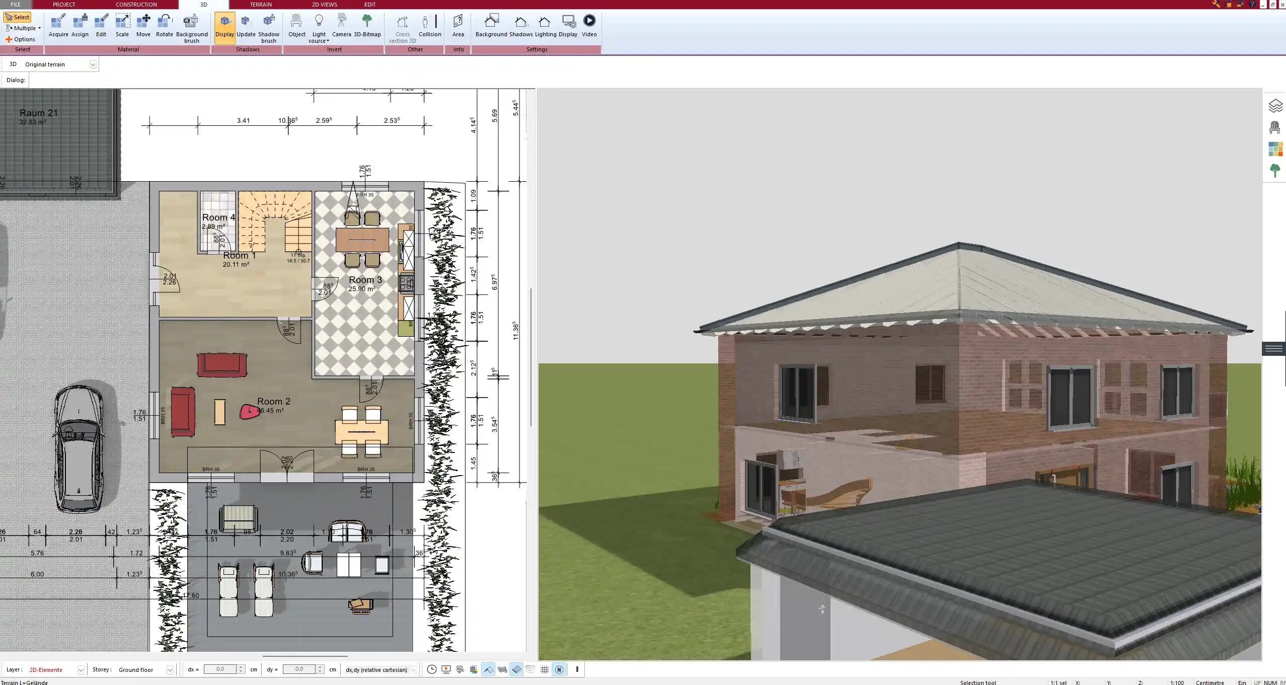
If you are using SketchUp: Open SketchUp → File → Import → change the file type dropdown to AutoCAD Files (.dwg, .dxf) → select your file → click Import → A dialog box appears you can set units here. Match this to the units in your CAD drawing.
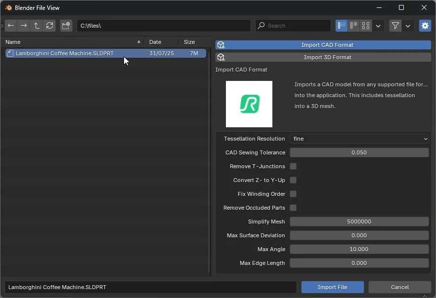
If you are using SolidWorks (.sldprt / .sldasm): Open SolidWorks → File → Open → select the part or assembly file → click Open.Your SolidWorks file will already have some 3D data — it is just a matter of refining and exporting it for visualization.
Result: Your CAD drawing is now open in a 3D-capable software environment, ready for cleanup.
Step 2: Clean the CAD Drawing Before You Convert Anything
Removing all the clutter from your CAD file that will break or complicate your 3D conversion. Think of a raw CAD drawing like a rough draft. It has dimension lines, text annotations, hatch patterns, overlapping edges from different design iterations, and duplicate geometry that never got deleted. None of that belongs in a 3D model. If you try to extrude over messy geometry, you will get broken surfaces, missing faces, and errors that take three times longer to fix than if you had just cleaned the file first.
Run these three commands in AutoCAD, in this exact order:
Step 2a Remove duplicate geometry: Type OVERKILL → press Enter → a dialog box opens → Leave default settings → click OK → AutoCAD scans your entire drawing and deletes every duplicate line, overlapping arc, and redundant geometry. You will see a count of deleted objects in the command line at the bottom.
Step 2b Fix internal file errors: → Type AUDIT → press Enter → when it asks “Fix any errors detected?” → type Y → press Enter → AutoCAD runs a file health check and auto-repairs corrupt objects. Check the command line — it tells you exactly how many errors it found and fixed.
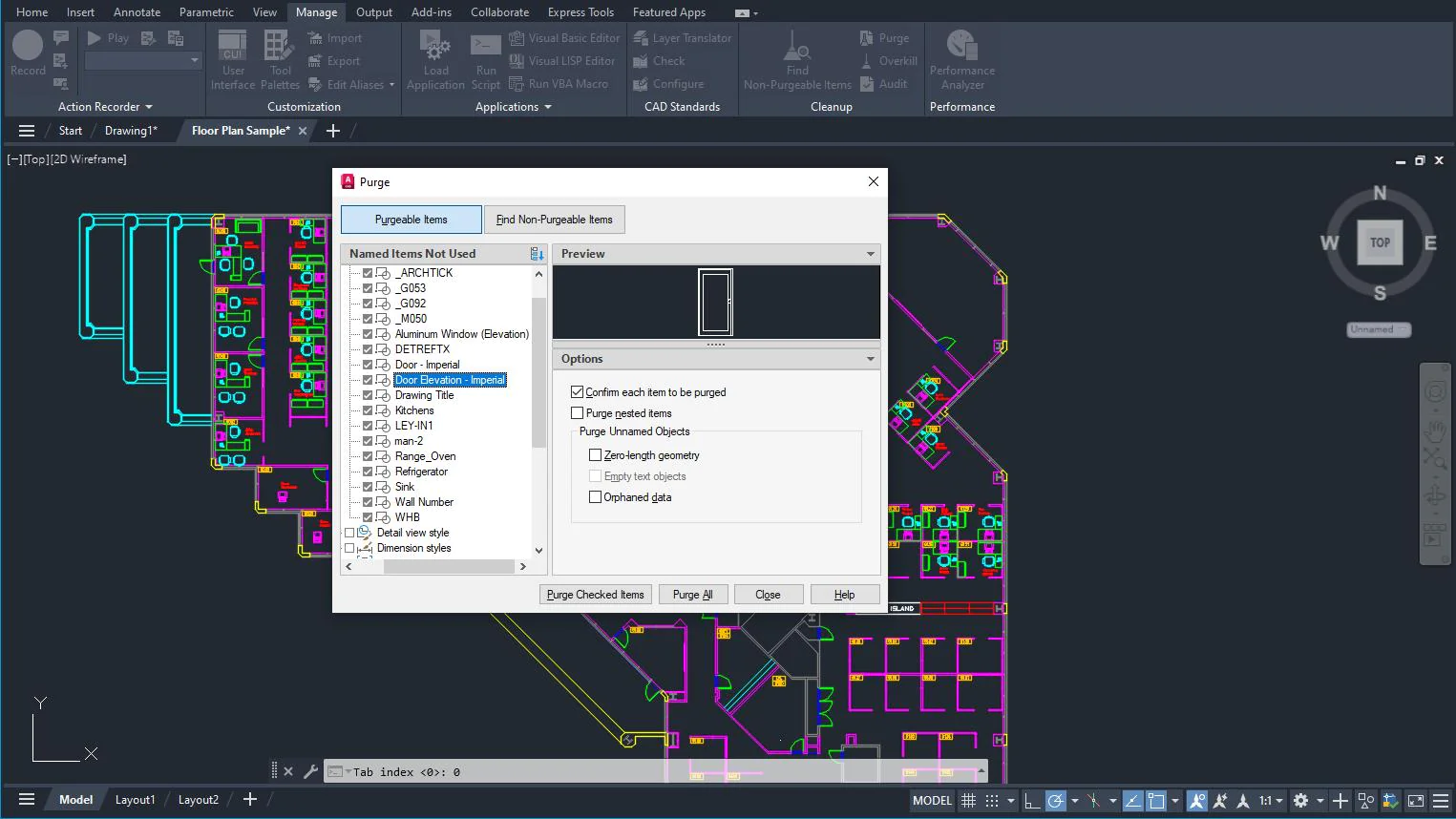
Step 2c Delete unused data: → Type PURGE → press Enter → in the Purge dialog, click Purge All → click Close → This strips out all unused blocks, layer definitions, linetypes, and text styles. Your file size drops noticeably.
Now delete layers you do not need in 3D: Open the Layer Properties Manager type LA → Enter) → Delete or freeze layers for: dimensions, text, hatching, title blocks, center lines, and reference grids → Keep only the actual geometry layers — walls, slabs, columns, openings, furniture outlines
In SketchUp, do this instead: Edit → Delete Guides to remove all guide points → Window → Layers → merge all loose geometry onto Layer 0 before exporting
Result: Lean, clean CAD drawing with only the geometry that belongs in your 3D model. No annotation clutter, no duplicates.
Step 3: Set the Correct Units and Scale
This is the step that catches most beginners off guard. You open your drawing in Blender or SketchUp, and your building looks like a postage stamp — or it fills the entire scene and you cannot even see it in the viewport. That happens because the software assumed one unit system and your file was drawn in another.
The fix is straightforward. Do it before you touch any geometry.
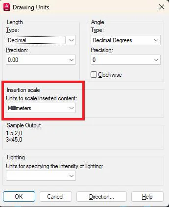
In AutoCAD —check and set drawing units: Type UNITS → press Enter → The Drawing Units dialog opens. Under Length, check the Type (Decimal, Architectural, etc.) and Insertion Scale → Set Insertion scale to match your drawing — Millimetres for metric projects, Inches for US-standard projects → Click OK
In SketchUp match units to your CAD source: Window → Model Info → Units → Set Format to Decimal and Precision to match your drawing’s level of detail → Change the unit to Millimetres or Metres (or Inches / Feet for US projects)
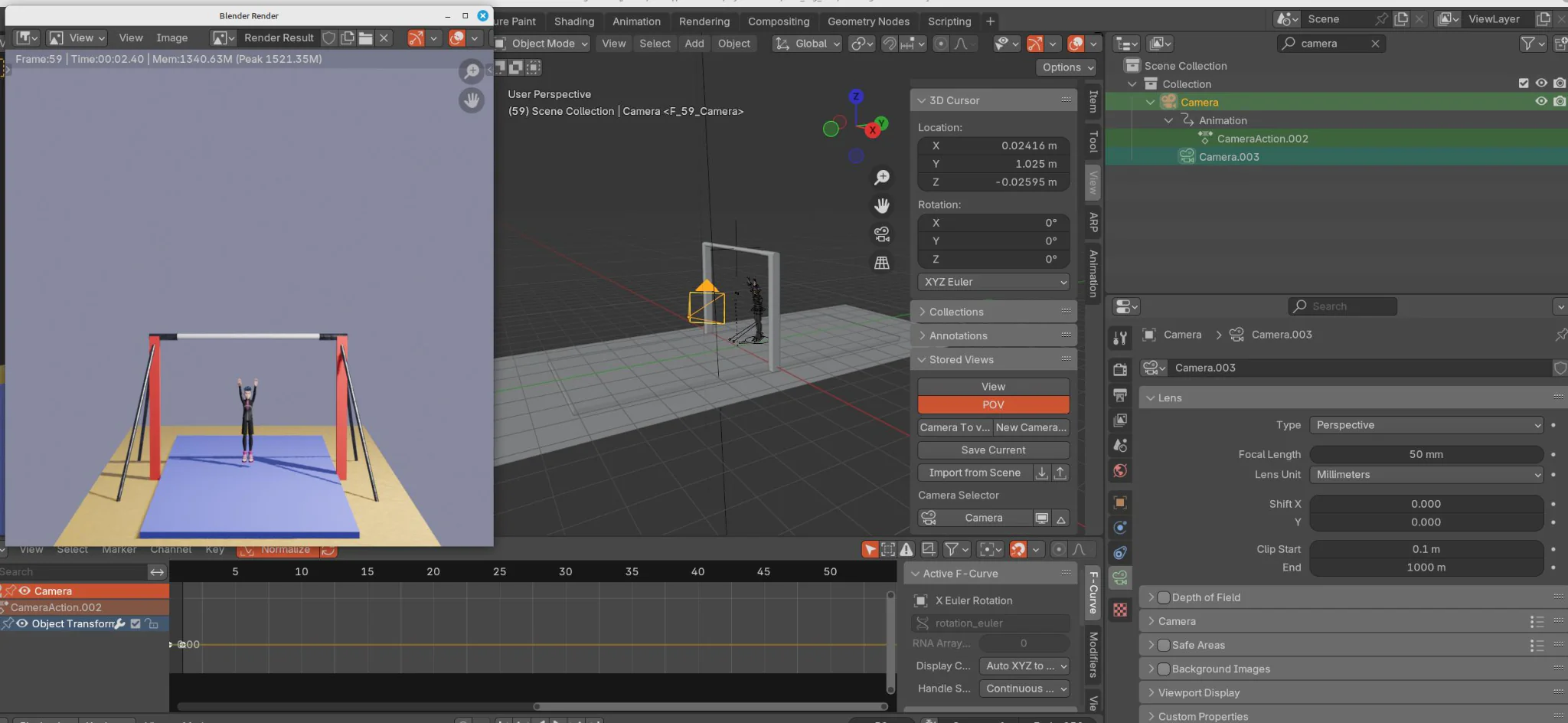
In Blender set the scene units correctly: Look at the right side panel in the Properties window → click the Scene Properties tab (the icon that looks like a cone and sphere) → Find Units section → set Unit System to Metric → set Unit Scale to 0.001 if your CAD file was drawn in millimetres → Why 0.001? Because Blender’s internal unit is 1 metre. One millimetre = 0.001 metres. Setting the scale here tells Blender to treat every 1mm in your file as the correct real-world size.
If your model still looks wrong after import, manually correct it: → In Blender, select your imported object → press S (scale) → type 0.001 → press Enter → This scales the object down by a factor of 1000, converting millimetre-scale geometry to metre-scale
Verification : In your 3D software, draw a line or rectangle using a dimension you know from the original drawing — say, a 3000mm (3-metre) wall length → Measure it using the software’s measuring tool → If the measurement matches, your scale is correct. If not, adjust and re-import.
Result: Model sits at exact real-world dimensions in the 3D viewport. A 3-metre wall measures 3 metres.
Step 4: Convert 2D Geometry into a 3D Model
Select your closed 2D shapes and push them into three dimensions. This is the core conversion step — flat linework becomes solid geometry with volume and height.
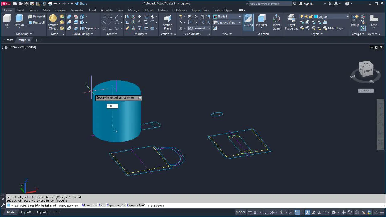
In AutoCAD: Switch workspace: bottom-right corner → select 3D Modeling → Type EXTRUDE → select closed shape → press Enter → type height value → press Enter → For curved forms: type REVOLVE or LOFT → For quick wall push: type PRESSPULL → hover over closed region → drag upward
In SketchUp: Press P to activate Push/Pull tool → click a face → drag upward → type exact height → press Enter → For profiles along a path (staircases, cornices): Tools → Follow Me → click profile face
In SolidWorks: Open 2D sketch → Insert → Boss/Base → Extrude → set depth value → click OK → For sheet metal: Insert → Sheet Metal → Base Flange
Result: Flat 2D drawing now has real depth, walls, and volume.
Step 5: Refine and Fix the 3D Geometry
Extruded geometry almost always has small errors — open edges, flipped normals, overlapping vertices. These cause render artifacts and broken surfaces later. Fix them now.
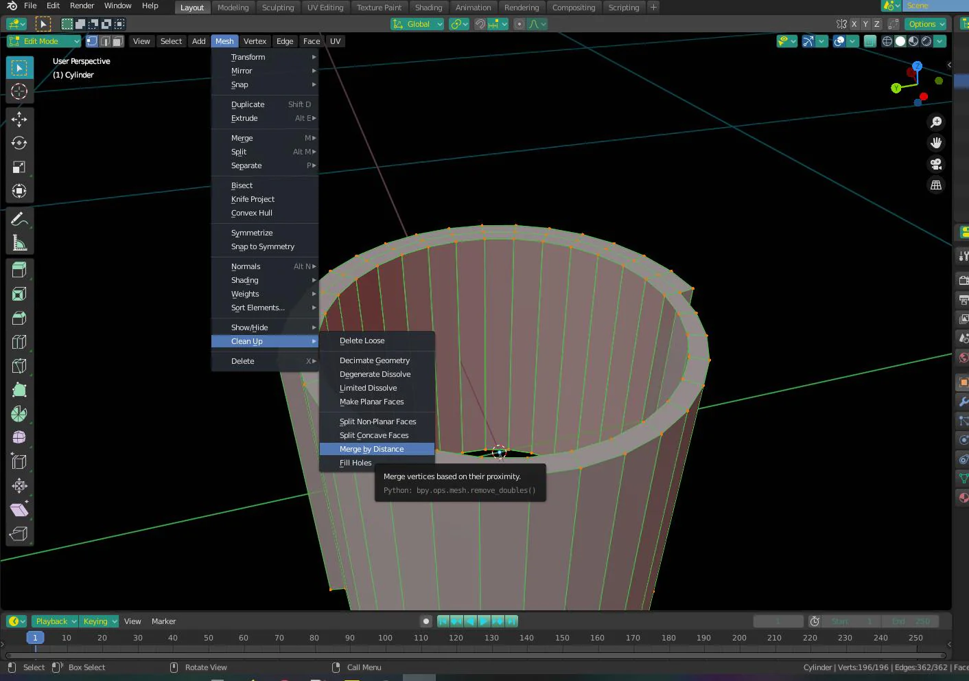
In Blender: Press Tab → Enter Edit Mode → Mesh → Merge by Distance → welds overlapping vertices → Press A (select all) → Alt + N → Recalculate Outside → flips all inverted normals outward → Mesh → Clean Up → Fill Holes → closes any open surface gaps
In SketchUp: Open Extension Warehouse → search and install Solid Inspector² (free) → Run Solid Inspector² → it flags every error → click Fix All
In SolidWorks: Tools → Evaluate → Check → runs full geometry health report → For imported STEP/IGES with surface gaps: Insert → Surface → Repair Bodies
Result: Clean, watertight mesh with no open edges, no flipped faces — ready for materials.
Step 6: Apply Materials to the 3D Model
Without materials, your entire 3D model renders as a uniform grey. Everything looks the same. Materials are what tell the render engine “this surface is polished concrete, this one is glass, this one is brushed steel.” They are not just decorative; they define how light bounces off each surface, which is what creates photorealism.
In Blender using the Principled BSDF shader:
The Principled BSDF is Blender’s master material. It covers almost every real-world surface in a single shader, which is why professionals use it for everything from skin to steel.
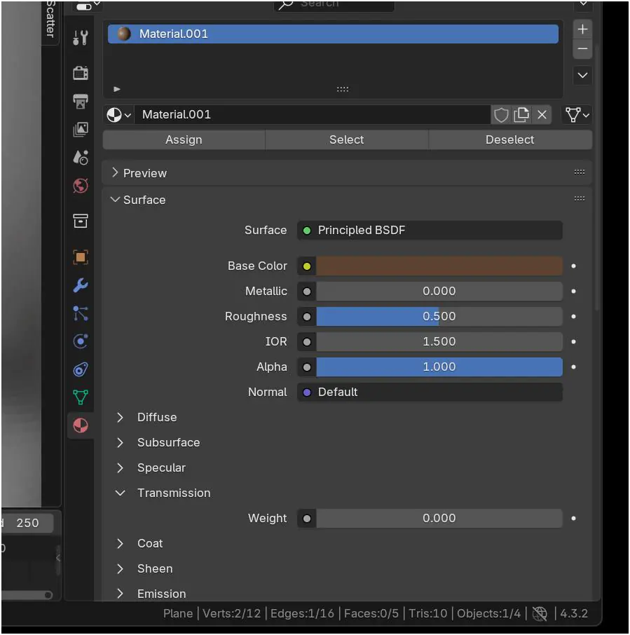
To assign a material: Select your object → look at the Properties panel on the right side → click the Material Properties tab (it looks like a grey sphere) → Click the + New button → a new material called “Material” appears → You will see the Principled BSDF settings below
Now adjust the properties:
Base Color : This is the main surface color or texture → Click the color swatch next to Base Color → pick a color from the color picker → For a texture (like wood or concrete): click the small dot to the left of Base Color → select Image Texture → click Open → browse to your texture file
Roughness : controls how shiny or matte the surface is → 0.0 = perfect mirror finish (polished chrome, glass) → 0.5 = semi-glossy (painted wall, smooth plastic) → 1.0 = completely matte (raw concrete, fabric)
Metallic : switches between metal and non-metal behavior → 0.0 = non-metal (plastic, wood, concrete, fabric) → 1.0 = metal (steel, copper, aluminium)
For glass specifically: → Set Transmission to 1.0 → Set Roughness to 0.0 for clear glass → Set IOR to 1.45 (standard glass refractive index)
In SketchUp + V-Ray material library workflow: → Open Extensions → V-Ray → Asset Editor → click the Materials tab → On the left panel, browse the V-Ray material library — it has categories like Stone, Wood, Metal, Glass, Fabric → Drag any material directly onto a surface in the viewport → it applies instantly → To customize: right-click the material in the Asset Editor → Edit → adjust Diffuse color, Reflection amount, Glossiness
In Lumion the fastest material workflow: → Click the Materials mode button in the top bar (looks like a paint bucket) → Click any surface in your scene → the right panel shows the full material library → Browse categories → click to apply → use the sliders to adjust Scale (texture size), Roughness, and Metallic intensity → For custom imported materials: click Custom → load your texture file
Result: Every surface in your model has a defined material. Concrete looks like concrete. Glass is transparent. Metal reflects. The model now communicates real material intent.
Step 7: Set Up Lighting and Scene for Visualization
Bad lighting kills a well-built model. Good lighting makes even a simple model look professional. Set the light source type based on whether you’re doing an interior or exterior scene.
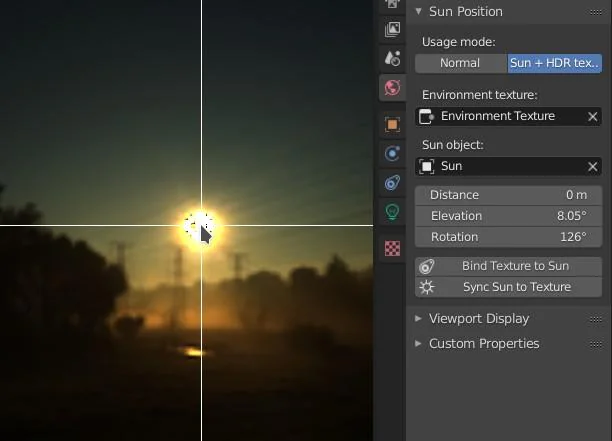
In Blender: Delete the default point light → Exterior scene: Shift + A → Light → Sun → rotate to set shadow angle → Interior scene: Shift + A → Light → Area → position behind window openings → HDRI Lighting: World Properties → Surface → Environment Texture → load HDRI file
In V-Ray (SketchUp or 3ds Max): V-Ray Asset Editor → Lights → enable V-Ray Sun for exterior daylight → Add Rectangular Lights inside window openings for interior fill → Adjust Exposure in the V-Ray Frame Buffer to control overall brightness
In Lumion: Sun Study tool → set date, time, and geographic location for accurate shadow angles → Objects tab → add Spotlights or Omni Lights for interior lamps
In Enscape: Enscape Settings → Visual Settings → Sky → select atmosphere type → Place Enscape light objects directly from the plugin panel
Result: Scene has directional lighting, defined shadows, and correct ambient fill for the scene type.
Step 8: Render the Final Output
The render engine converts your 3D scene into a finished image or animation. Sample count controls quality low samples = fast preview, high samples = final output.
In Blender (Cycles engine): Render Properties → Render Engine → Cycles → Set Samples: 128 for test renders / 512–1024 for final output → Press F12 to render a still image → Image → Save As → choose PNG or EXR → save → For animation: Render → Render Animation → outputs full frame sequence
In V-Ray: Open V-Ray Frame Buffer → set output Width × Height (minimum 1920×1080 for presentations) → Click Render → noise level drops progressively — stop when clean → File → Save Image from the Frame Buffer
In Lumion: Switch to Photo or Movie mode → Select effect preset (Real Skies, Hyperlight) → adjust sliders → Click Render Photo or Render Movie → Lumion saves to desktop folder automatically
In Enscape: Click Render Screenshot in the Enscape toolbar for a still image → Video Editor → set camera path and speed → click Export → saves as MP4
Result: Final render image or animation file saved to your drive — ready for presentation or delivery.
Step 9: Export the 3D Model in the Required Format
Export in the format your client, printer, or downstream software needs. Wrong format = compatibility failure on the receiving end.
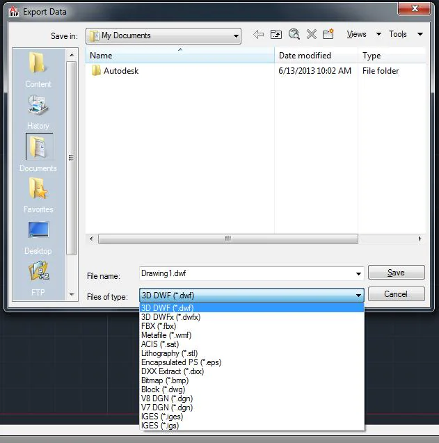
From AutoCAD: Type EXPORT → select format (DWG, DXF, STL, FBX) → name file → Save
From Blender: File → Export → choose format → OBJ: check Include Materials + Write MTL File in export options → FBX: set Path Mode → Copy → click embed textures icon → export
From SolidWorks: File → Save As → change file type to STL, STEP, IGES, or OBJ → For STL: set Resolution → Fine in the export options dialog → click OK
From SketchUp: →File → Export → 3D Model → choose OBJ or FBX → Check Export Two-Sided Faces prevents missing geometry on import
Result: Clean, format-correct 3D model file ready for client delivery, 3D printing, or game engine import.
Tools Required for CAD to 3D Model Conversion
|
Software |
Role in Workflow |
| AutoCAD | CAD source file, geometry cleanup, initial 3D extrusion |
| SolidWorks | Part and assembly modeling, engineering-grade extrusion |
| SketchUp | Architectural modeling, fast Push/Pull extrusion |
| Blender | Full 3D modeling, geometry repair, Cycles rendering |
| Lumion | Real-time architectural visualization, fast rendering |
| V-Ray | Photorealistic rendering inside SketchUp, 3ds Max, or Rhino |
| Enscape | Real-time visualization inside Revit, SketchUp, and Rhino |
Common Problems and How to Fix Them
Scale Mismatch
Problem: Your model imports at the wrong size a building appears as a tiny object or stretches past the visible viewport.
Fix: In Blender: select the object → press S → type 0.001 → press Enter (for mm-to-metre conversion) → In SketchUp: Window → Model Info → Units → reset the format and unit to match the original CAD source → Always verify with a known reference dimension after every import
Broken Geometry
Problem: After extrusion, surfaces intersect each other, faces disappear randomly, or the mesh collapses in certain areas.
Fix: In AutoCAD (before export): type OVERKILL → then AUDI these two commands together catch 90% of geometry problems before they reach your 3D software → In Blender (after import): Tab into Edit Mode → Mesh → Merge by Distance → merges overlapping vertices causing collapse
Open Surfaces
Problem: Your 3D model has visible holes in areas where geometry did not close during extrusion or import.
Fix: In Blender: Tab into Edit Mode → select the open edge loop (Alt + click the border edge) → press Alt + F to fill with a face → In SketchUp: run Solid Inspector² (Extensions menu) → click Fix All it auto-patches open surfaces it can solve.
Missing Faces
Problem: Certain faces do not appear in the viewport or render black in the output image.
Fix: This is an inverted normals problem. The face exists it is just pointing the wrong direction. In Blender: Tab into Edit Mode press A to select all Alt + N Recalculate Outside Every face in the mesh flips to the correct outward direction in a single operation → To confirm: enable Face Orientation in the Viewport Overlays all faces should show as blue (outward), not red (inward).
Export Formats at a Glance
| Format | Best Use Case |
| OBJ | General 3D software exchange carries geometry and material (.mtl) data; works in Blender, 3ds Max, Maya, Cinema 4D |
| FBX | Game engines and animation supported by Unity, Unreal Engine, Lumion; carries geometry, materials, and animation rigs |
| STL | 3D printing only geometry data with no material, color, or texture information; every 3D printer and slicer reads it |
| DWG | AutoCAD and architectural handoff preserves CAD layer structure, dimensions, and annotation data for continued design work |
Final Output: What You Get at the End of This Workflow
Completing this 9-step workflow gives you a professional 3D visualization package ready for real-world use, including photorealistic render images (PNG, JPEG, or EXR) for presentations and marketing, walkthrough animations (MP4) for architectural and product demonstrations, exportable 3D models (OBJ, FBX, STL) for editing, game engines, or 3D printing, and clean CAD files (DWG/DXF) for engineering and project handover. This process is widely used in architecture, product design, and engineering to convert flat CAD drawings into accurate and realistic 3D visuals before actual construction or manufacturing.