


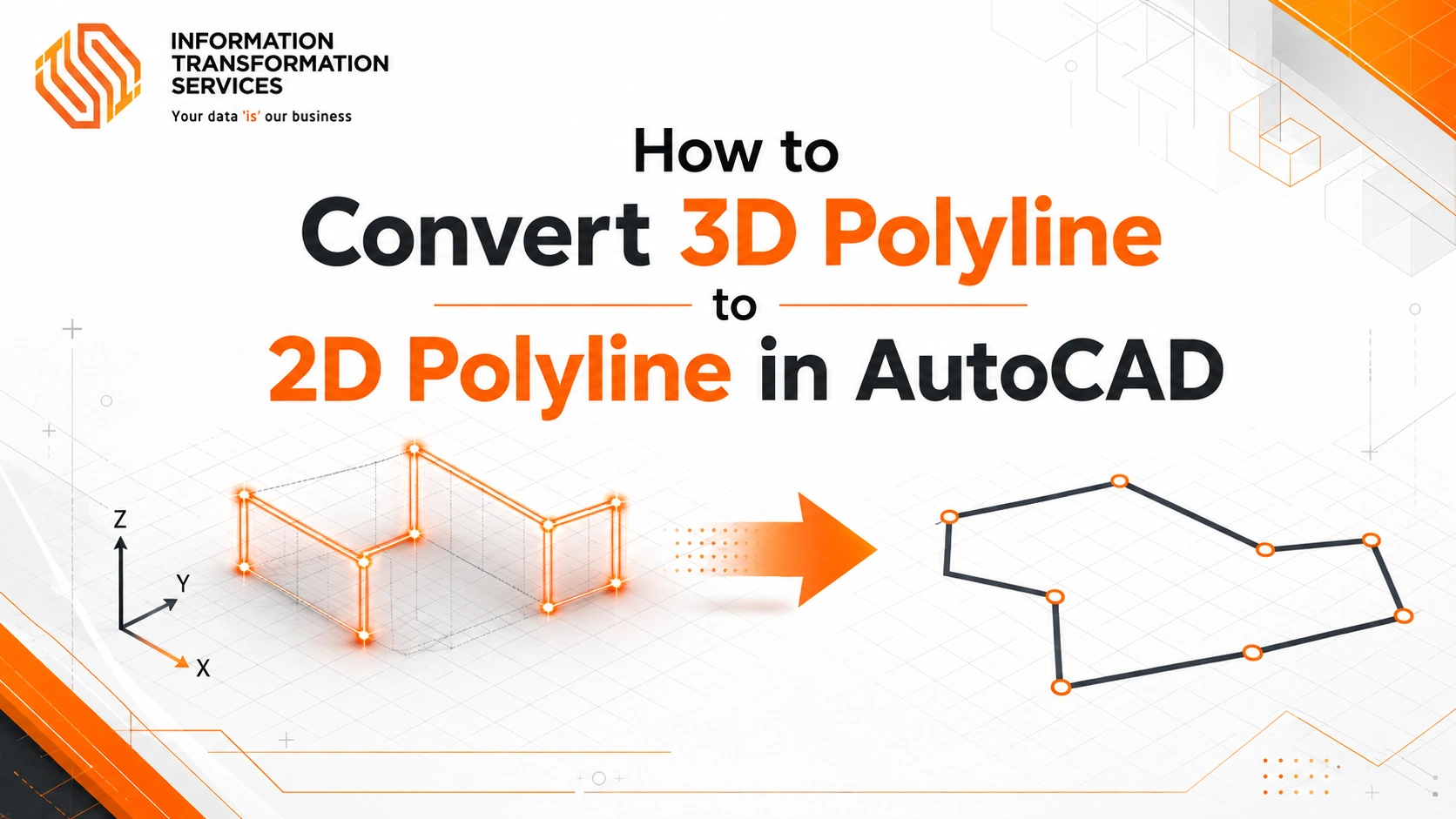
How to Convert 3D Polyline to 2D Polyline in AutoCAD
The fastest way to convert a 3D polyline to a 2D polyline in AutoCAD is by using the FLATTEN command. Select the 3D polyline, type FLATTEN, and press Enter. When AutoCAD asks whether to remove hidden lines, type N and press Enter. AutoCAD then converts the object into a flat 2D polyline by setting all Z-values to zero.
If the FLATTEN command isn’t available, such as in AutoCAD LT, you can use EXPLODE followed by PEDIT with the Join option. Another option is to trace a new boundary using the BOUNDARY command. If you’re using Civil 3D, the Convert 3D to 2D Polylines tool converts 3D polylines to 2D while preserving their actual elevation instead of flattening them to zero.
You extract a section, terrain path, or pipe run from your project, and AutoCAD creates a 3D polyline instead of a standard flat line. Then the problems begin. You try to apply a dashed centerline, but it doesn’t display correctly. You attempt to hatch the shape, but the boundary won’t close. Meanwhile, your client needs a flat, printable plan sheet, yet the line keeps rising and falling in elevation with no clear way to fix it other than redrawing everything manually.
Who Runs Into This Problem Most Often
Civil Engineering and Site Design
Civil engineers regularly extract cross-sections and corridor data from grading and roadway models. This data almost always comes out as 3D polylines. Converting it to 2D makes it usable for construction plan sheets and quantity takeoffs.
Land Surveying
Surveyors import boundary lines, point data, and contour information that includes real elevation values. Since legal plats and boundary drawings require flat 2D lines, converting 3D polylines is a routine part of turning field data into finished drawings.
Architecture and Site Planning
Architects working on sloped sites or with integrated terrain models often receive 3D polylines from civil consultants. Flattening these polylines keeps floor plans and site plans clean, accurate, and easy to dimension.
MEP and Utility Drafting
MEP teams frequently model pipe runs, conduit paths, and utility lines in 3D to track elevation changes. They then flatten these polylines to create 2D riser diagrams, isometric drawings, and utility plans.
GIS and Mapping Work
Contour lines and utility data exported from GIS software often include elevation as 3D polylines. Flattening them allows the data to fit correctly into a standard 2D basemap.
3D Polyline vs 2D Polyline: What’s Really Different
A 3D polyline stores X, Y, and Z coordinates for every point along the line, allowing it to move up, down, and sideways in true 3D space. You create one with the 3DPOLY command. These polylines are commonly found in survey data, terrain sections, and pipe runs with changing elevations.
A 2D polyline, which AutoCAD calls an LWPOLYLINE (short for lightweight polyline), stores only X and Y coordinates. Every point stays at the same elevation, making it ideal for standard 2D drafting. You create one with the PLINE command, and it is the object type AutoCAD expects for plans, sections, hatch boundaries, and detailed views.
| Property | 3D Polyline | 2D Polyline (LWPolyline) |
|---|---|---|
| Coordinates stored per point | X, Y, and Z | X and Y only, at one flat elevation |
| Command used to draw it | 3DPOLY | PLINE |
| Supports width | No | Yes |
| Supports arcs (curved segments) | No | Yes |
| Displays dashed or center linetypes correctly | Usually no | Yes |
| Common source | Survey points, 3D models, corridor sections | Manual 2D drafting and imported 2D data |
Here’s why this matters in everyday drafting. When you assign a dashed or center linetype to a 3D polyline, AutoCAD often displays it as a solid line. Dash patterns are designed to follow a flat plane, and changes in elevation can interrupt how they appear. If you’ve imported survey or terrain data and tried to prepare it for a plan sheet, you’ve likely encountered this issue. Converting the object to a 2D polyline usually fixes it immediately.
Why You Need to Convert a 3D Polyline to 2D in AutoCAD
- Linetypes don’t display correctly. Dashed and center linetypes usually work properly only on 2D polylines.
- The line came from survey or terrain data. Survey, terrain, and grading data is often imported as 3D polylines. Converting it to 2D makes it easier to use for standard drafting.
- You need more editing options. Unlike 3D polylines, 2D polylines support line widths and curved (arc) segments.
- You’re creating a 2D plan or section for printing. Before you can produce a clean, printable drawing, the 3D geometry needs to be converted into standard 2D drafting geometry.
- Another AutoCAD command won’t accept the object. Some tools, including certain hatch boundaries, area calculations, and block operations, work only with standard 2D polylines.
Benefits of Converting a 3D Polyline to 2D
- Smaller, faster files. A 2D polyline (LWPolyline) stores less data per point than a 3D polyline, helping keep large drawings lighter and faster to open.
- Linetypes display correctly. Dashed, center, and other linetypes, along with hatch patterns, appear as expected on 2D polylines.
- Better command compatibility. Commands such as HATCH, AREA, and OFFSET work more reliably with 2D polylines and avoid many of the issues that can occur with 3D polylines.
- Easier editing. 2D polylines support line width, curved (arc) segments, and simple grip editing, features that are not available with 3D polylines.
- Cleaner drawing handoff. Converting to 2D creates geometry that matches most CAD standards and client templates, reducing revisions and making plan sheets easier to review and share.
Which Conversion Method Fits Your Drawing?
| Your Situation | Best Method |
|---|---|
| You have the full version of AutoCAD (not LT) and want the fastest solution. | FLATTEN |
| You’re using AutoCAD LT, which doesn’t include FLATTEN. | EXPLODE + PEDIT (Join) |
| You want to create a new 2D polyline without modifying the original. | BOUNDARY |
| You’re using Civil 3D and want to preserve the actual elevation. | Convert 3D to 2D Polylines (CONVERT3DPOLYS) |
| Your polyline has a single elevation value. | Edit it in the Properties palette. |
| You regularly convert 3D polylines and want to automate the process. | Use an AutoLISP routine. |
| You have a short polyline with only a few vertices. | Edit it manually using grips. |
First, Check If Your Polyline Is Really 3D
Before converting anything, make sure the object is actually a 3D polyline. Sometimes a line only appears three-dimensional because of the current viewing angle, even though it’s already flat.
- Look at the bottom of the AutoCAD window to find the Command Line, where you enter commands and view AutoCAD’s responses.
- Type LIST and press Enter.
- Move your cursor over the polyline and left-click to select it. The object will highlight, usually in blue, with small square grips at each vertex, confirming that AutoCAD has selected it.
- Press Enter again to run the command.
- AutoCAD opens the Text Window, which displays details about the selected object, including its type, layer, color, and the X, Y, and Z coordinates for each vertex.
- Check the Z values:
- If every Z value is 0.0000, the polyline is already flat.
- If the Z values are different, the object is a true 3D polyline and needs to be converted.
- Close the Text Window by pressing F2 or clicking the X in the upper corner.
The FLATTEN Command: The Fastest Way to Convert a 3D Polyline to 2D
FLATTEN is the quickest way to convert a 3D polyline into a 2D polyline. It is included with Express Tools in the full Windows version of AutoCAD. It is not available in AutoCAD LT or AutoCAD for Mac.
Before you begin:
The FLATTEN command permanently removes the Z-values from the selected object. After you save the drawing, those elevation values cannot be restored. To avoid losing the original data, copy the 3D polyline to a separate layer with a clear name, such as 3D-BACKUP, before making any changes.
Steps
- In the bottom-right corner of the AutoCAD window, click the Workspace Switching (gear) icon.
- Select Drafting & Annotation. The ribbon switches to the standard 2D drafting workspace.
- Type PLAN in the Command Line and press Enter.
- When AutoCAD displays Enter an option [Current ucs/Ucs/World] :, press Enter again to accept the default setting. The view changes to a top-down orientation, making it easier to see the final result.
- Select the 3D polyline by clicking it once.
- Type FLATTEN and press Enter.
- When prompted with Remove hidden lines? [Yes/No] :, type N and press Enter. This keeps all line segments visible instead of hiding any that overlap.
- AutoCAD converts the object immediately. Although the shape may look the same in the top view, all of its Z-values are now set to 0.
How to Check the Conversion
- Select the converted object.
- Press Ctrl + 1 to open the Properties palette.
- At the top of the palette, confirm that the object type is Polyline instead of 3D Polyline.
- Check the Elevation property. It should display a single value, typically 0.
- Run the LIST command again and verify that every Z-value is 0.0000.
Tip: You can convert multiple 3D polylines at the same time. Select all the objects you want to convert by holding Shift while clicking each one or by dragging a selection window around them. Then run FLATTEN once to convert them all.
No FLATTEN on Your System? Use EXPLODE and PEDIT Join
Use this method if you’re working in AutoCAD LT, if FLATTEN doesn’t produce the expected result, or if you want more control over how the final 2D polyline is created.
Steps
- Select the 3D polyline by clicking it once. It will highlight with grips at each vertex.
- Type EXPLODE and press Enter. AutoCAD breaks the 3D polyline into individual line segments. The drawing may look the same, but the object is no longer a single polyline.
- Click one of the segments. If only that segment highlights instead of the entire shape, the EXPLODE command worked.
- Type PEDIT and press Enter.
- When prompted to Select polyline or [Multiple]:, click one of the line segments.
- AutoCAD displays the message: Object selected is not a polyline. Do you want to turn it into one? . Press Enter to accept Yes.
- When the PEDIT options appear, type J for Join and press Enter.
- Select the remaining line segments by clicking them individually or by dragging a selection window around the entire shape. Press Enter to confirm.
- AutoCAD reports how many segments were added to the polyline, confirming that the join was successful.
- Press Enter again or press Esc to exit the command.
You now have a single 2D polyline created from the original line segments. If the object is still at a nonzero elevation, press Ctrl + 1 to open the Properties palette and set the Elevation value to 0.
Working in Civil 3D? Use Convert 3D to 2D Polylines
Civil 3D users often encounter this issue after extracting sections or profiles from a surface, corridor, or alignment. These objects are typically created as 3D polylines. Fortunately, Civil 3D includes a dedicated command to convert them into 2D polylines.
Steps
- Click the Modify tab on the ribbon.
- In the Design panel, click Convert 3D to 2D Polylines. Alternatively, type CONVERT3DPOLYS in the Command Line and press Enter.
- When prompted to Select 3D polylines, select the objects you want to convert. You can click them individually or drag a selection window around multiple polylines.
- Press Enter to start the conversion.
- Review the result. The new 2D polyline is placed at the elevation of the original polyline’s starting point, rather than being flattened to 0. This preserves a meaningful elevation reference, which is especially useful when working with multiple sections or profiles that need to remain linked to real-world heights.
Verify the Conversion
- Select the converted object.
- Press Ctrl + 1 to open the Properties palette.
- Confirm that the object type is now listed as Polyline instead of 3D Polyline.
Need a Clean Copy Instead? Trace It With the BOUNDARY Command
If you want to keep the original 3D polyline unchanged, use the BOUNDARY command. It creates a new 2D polyline that traces the visible shape without modifying or deleting the original object. This method works only with closed shapes.
Steps
- Type PLAN in the Command Line and press Enter. Press Enter again to accept the default option and switch to a top-down view.
- Type BOUNDARY (or BPOLY) and press Enter. The Boundary Creation dialog box opens.
- In the dialog box, make sure Object Type is set to Polyline. This is the default setting.
- Click Pick Points.
- Click once inside the closed area formed by the 3D polyline.
- AutoCAD analyzes the surrounding edges and displays a dashed preview of the boundary it detects.
- Press Enter to create the boundary.
AutoCAD creates a new 2D polyline that matches the visible boundary at zero elevation. The new polyline is placed directly on top of the original 3D polyline, which remains unchanged.
After confirming that the new polyline is correct, you can move the original 3D polyline to a backup layer or delete it if it is no longer needed.
Note: The BOUNDARY command works only with closed shapes or shapes that appear closed from the current view. It cannot create a boundary from an open polyline.
Manual Fix: Editing Z-Values in the Properties Palette
This method is best for simple objects or for AutoCAD LT users who need to correct the elevation of a line, arc, or circle with a single Z-value. While it can also be used for 3D polylines, it becomes time-consuming when the object contains many vertices at different elevations.
For Simple Objects With One Elevation Value
- Select the object.
- Press Ctrl + 1 to open the Properties palette.
- In the Geometry section, locate the Start Z field. If the object has additional elevation fields, such as End Z or Center Z, locate those as well.
- Click each Z-value, enter 0, and press Enter.
For a 3D Polyline With Multiple Vertice
- Select the 3D polyline.
- Press Ctrl + 1 to open the Properties palette.
- In the Geometry section, locate the Vertex field. It displays the current vertex number (such as Vertex 1, Vertex 2, and so on) with arrows to move between vertices.
- With Vertex 1 selected, find the Z field, change its value to 0, and press Enter.
- Use the arrow to move to Vertex 2, then repeat the process.
- Continue until every vertex has a Z-value of 0.
This method provides complete control over each vertex, but it can be slow for complex polylines with many points. For larger objects, FLATTEN or EXPLODE followed by PEDIT Join is usually much faster.
Converting Often? Automate It With an AutoLISP Routine
If you regularly convert 3D polylines and don’t have Express Tools or Civil 3D, an AutoLISP routine can automate the process. After it’s loaded, you can convert 3D polylines with a single command. Only download LISP files from trusted sources, such as Lee Mac Programming or CADTutor. Never run scripts from websites you don’t recognize.
Steps
- Download a tested AutoLISP routine designed to flatten 3D polylines by setting their Z-values to zero. Before using it, read the instructions provided by the author.
- Save the .lsp file in a location on your computer where you can easily find it.
- In AutoCAD, type APPLOAD in the Command Line and press Enter. This opens the Load/Unload Applications dialog box.
- Browse to the .lsp file, select it, and click Load.
- Close the dialog box.
- Check the routine’s documentation to find its command name. Type that command in the Command Line and press Enter.
- Select the 3D polylines you want to convert and press Enter. The routine runs and sets the Z-value of every vertex to 0.
Grip Editing by Hand: Best for Short Polylines Only
This is the slowest conversion method, but it works well for 3D polylines with only a few vertices.
Steps
- Select the 3D polyline. Small square grips appear at each vertex.
- Click the first grip to activate it. The grip changes color (typically red), indicating that it is selected.
- Use the coordinate tooltip or command input to enter a new coordinate with the same X and Y values and a Z-value of 0, then press Enter.
- Repeat the process for each remaining grip until every vertex has a Z-value of 0.
- Press Esc when you’re finished.
This method is practical only for very short polylines. If the object has more than a few vertices, using FLATTEN, EXPLODE with PEDIT Join, or another conversion method will save you significant time.
Common Problems After Converting a 3D Polyline
The linetype still appears as a solid line
This is usually a display setting rather than a conversion issue. Check the LTSCALE and PSLTSCALE values. If the linetype scale doesn’t match your drawing units, dashed and center linetypes may appear solid even on a correctly converted 2D polyline.
FLATTEN doesn’t seem to do anything
Make sure you selected the correct object. FLATTEN behaves differently with 3D solids, meshes, and objects inside blocks. If the polyline is part of a block, explode the block first, then run FLATTEN on the polyline.
AutoCAD displays “Unknown command” when you type FLATTEN
This usually means Express Tools isn’t available or hasn’t been loaded. Verify that you’re using the full Windows version of AutoCAD rather than AutoCAD LT or AutoCAD for Mac. Then type EXPRESSTOOLS and press Enter to load the Express Tools menu. If the command is still unavailable, check whether Express Tools was installed with your AutoCAD installation.
LIST still shows different Z-values
If the LIST command still reports different Z-values, the conversion may not have completed, or you may have selected the wrong object. Run LIST again and make sure you’re checking the correct polyline.
You need the original elevation data back
Once you run FLATTEN and save the drawing, the original Z-values cannot be restored. That’s why it’s important to create a backup copy of the 3D polyline before converting it.
Tips From Everyday Drafting Work
- Create a backup first. Before running FLATTEN, copy the 3D polyline to a backup layer. This simple step helps prevent the most common mistake—losing the original elevation data.
- Convert multiple polylines at once. Select all the 3D polylines you want to convert before running FLATTEN. This is much faster than converting each object individually.
- Check your UCS. FLATTEN works on the current UCS plane. If your UCS has been rotated or changed, reset it to the World UCS before converting to avoid unexpected results.
- Verify the conversion. After converting, press Ctrl + 1 to open the Properties palette and confirm that the object type is Polyline instead of 3D Polyline. It only takes a few seconds and helps catch mistakes early.
- Review your linetype scale. Even after a successful conversion, dashed and center linetypes may not display correctly if LTSCALE doesn’t match your drawing units.
Related Tasks You Might Need Next
Convert a 2D Polyline to a 3D Polyline
If you need to reverse the process, Civil 3D includes the Convert 2D to 3D Polylines tool on the Modify tab in the Design panel. The new 3D polyline can take its elevation from a surface, contour data, or selected points.
Join Multiple 3D Polylines
To combine connected 3D polyline segments into a single object, you do not need to flatten them first. Use the JOIN command, which works directly with 3D polylines and is also available in AutoCAD LT.
Extract Elevation Data
If you need station and elevation information for a report rather than a drawing, use the DATAEXTRACTION command. It reads the coordinates of each vertex and exports the data to a table or spreadsheet.
Understand the Difference Between a 3D Polyline and a Surface
In Civil 3D, a 3D polyline is a single line that follows points in 3D space, while a surface is a triangulated model built from many interconnected points. Sections and profiles are typically created as 3D polylines rather than surfaces, which is why converting them to 2D is a common step in corridor and grading projects.
Wrapping Up: Choosing the Right Method for Your Drawing
Converting a 3D polyline to a 2D polyline in AutoCAD is simply a matter of choosing the method that fits your workflow. FLATTEN is the fastest option in the full version of AutoCAD. EXPLODE followed by PEDIT Join is a reliable alternative for AutoCAD LT and offers more control over the final result. BOUNDARY creates a new 2D polyline without changing the original object, while CONVERT3DPOLYS is the best choice in Civil 3D when you want to preserve a meaningful elevation.
For special cases, you can also use the Properties palette, an AutoLISP routine, or manual grip editing. Whichever method you choose, create a backup of the original 3D polyline before converting it. Once the elevation data is removed and the drawing is saved, it cannot be recovered.