How to Set Up a 3ds Max Scene for Architectural Visualization
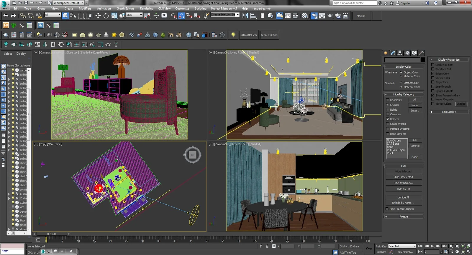
Starting your first project in Autodesk 3ds Max can feel confusing at first. The software comes with many tools, settings, and panels that new users often find difficult to understand. Simple tasks like creating walls, importing floor plans, or setting up lighting can take extra time when you are new to architectural design.
This beginners guide to architectural modeling in 3ds max will help you create a clean and organized scene from the start. You will understand how to arrange your workspace, use the correct scale, manage layers, import blueprints properly, and prepare realistic lighting for architectural visualization. A well-structured scene improves both performance and render quality.
Whether you are designing interiors, exteriors, or complete building concepts, a proper scene setup helps you work faster and avoid common mistakes. By following the right process, you can create professional-looking architectural renders with better detail, smoother navigation, and more efficient results in 3ds Max.
Understanding Autodesk 3ds Max for Architecture
To build a great rendering, you first need to understand why Autodesk 3ds Max is the industry standard. While there are simpler 3D programs out there for quick sketches, high-end visualization studios almost always use this software when they need to create hyper-realistic, magazine-quality images of buildings and interiors.
Essentially, it acts as the bridge between flat architectural blueprints and rich, three-dimensional presentations that make a client feel like they are already walking through a space.
When it comes to professional architecture modeling in 3ds max, the software excels in four major areas:
- Seamless Blueprint Integration: You rarely have to build walls from pure guesswork. You can import 2D drawings (DWG files) or 3D data directly from programs like AutoCAD or Revit. The software respects your original coordinates and keeps your real-world dimensions perfectly intact.
- Total Modeling Freedom: Whether you are building massive structural columns, complex roofs, or the tiny fabric folds on a custom sofa, the tools give you complete control over your geometry. You aren’t limited by rigid, pre-made object blocks.
- Photorealistic Lighting and Materials: When paired with top-tier rendering engines like V-Ray or Corona, the software accurately calculates how light bounces in the real world. It mimics exactly how sunlight hits a concrete floor, how glass reflects surroundings, and how soft shadows pool in the corners of a room.
- Flexible Client Edits: Clients change their minds constantly. If a client looks at a draft and decides they want to swap out a dark wooden floor for a polished tile texture, the software allows you to make these changes to your materials without having to rebuild the entire structural model from scratch.
Setting Up Your Workspace: UI and Essential Preferences
Now that you understand why the software is so powerful, the next step is preparing your environment. Setting up your digital workspace before drawing a single wall is the difference between a smooth project and hours of technical frustration. When prepping a fresh scene, professional workflows always focus on three major interface adjustments:
1. Configure Your Unit Setup
The absolute first thing you must do with a blank scene is lock in your units. If you skip this, your physical lighting will look completely wrong later, and imported models will either be microscopic or the size of a planet.
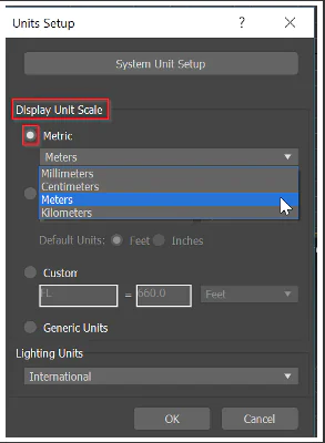
- Display Unit Scale: Go to Customize > Units Setup and set your Display Unit Scale to your preferred measurement (such as Centimeters or Meters). This controls what you see on your screen.
- System Unit Setup: Don’t stop there, click the System Unit Setup button at the top of that same menu. Ensure that 1 Unit equals 1.0 Centimeter (or your matching working unit). This tells the software’s physics engine how to calculate actual distances, light bounces, and material sizes accurately.
2. Streamline the Interface for Extra Screen Space
3ds Max comes with a lot of toolbars turned on by default that are meant for video game design or character animation. For architectural visualization, you want as much clear viewport space as possible.
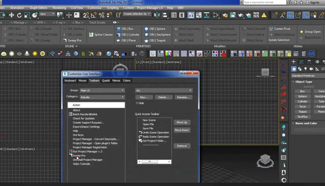
- Hide the Bloat: Go to Customize > Show UI and turn off the Ribbon or the ViewCube if you find them distracting. They take up valuable visual real estate.
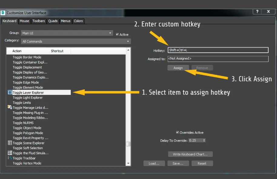
- Organize Your Hierarchy: Open your Scene Explorer and Layer Explorer, then dock them to the left side of your screen. This gives you a clean list where you can instantly toggle the visibility of your walls, furniture, ceilings, and plants with a single click.
3. Change These Crucial Preferences
A few default factory settings inside the software can actively hurt your workflow when you begin dealing with heavy architectural data. You want to adjust these to prevent lagging and crashes.
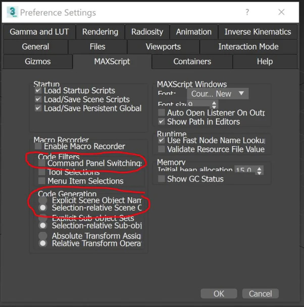
- Boost Your Undo History: Go to Customize > Preferences and open the General Tab. Change your Scene Undo levels from the default 20 up to 50 or higher. When you make a mistake on a complex shape, you want plenty of room to back up.
- Smart Auto-Backups: Switch to the Files Tab. Set your Auto Backup interval to every 20 or 30 minutes. Heavy interior scenes with millions of polygons can cause a brief stutter when saving. Setting this to a slightly longer window stops the software from interrupting your creative flow every five minutes while still keeping your file safe.
- Kill Selection Highlighting: In the Viewports Tab, turn off the hover highlight effect (the bright yellow outline that appears over objects when your mouse moves past them). In large, detailed scenes, your computer can freeze up just trying to calculate that yellow line over a high-polygon couch or tree.
4. Lock in Your Custom Preset
Once your workspace feels clean and professional, you want to make sure it stays that way every single time you launch the program.
- Save Your Layout: Use the Save Custom UI Scheme option to create your own personal preset.
- The Modern Advantage: Recent updates to the software now save your menus and hotkey adjustments as simple “delta” preference files in your local User Settings folder. This means if your software ever glitches and you have to reset your main configurations, your custom layout changes are safely stored outside the crash zone and can be carried over instantly without rebuilding them from scratch.
The 3ds Max Architectural Modeling Pipeline
Now that your workspace is clean and your blueprints are locked in place, you are ready to start building. Instead of guessing what to do next, you should follow a reliable, step-by-step pipeline. This keeps your file running fast and ensures you don’t have to constantly redo your work later.
Step 1: Building the Core Structural Shell
The very first physical things you need to build are the bare bones of your space: the main walls, the floor, and the ceiling.A common mistake many beginners make here is trying to build a room out of separate 3D boxes and smashing them together like building blocks. This is a nightmare because it creates messy overlapping faces, makes your file heavy, and makes it almost impossible to cut clean window openings later.
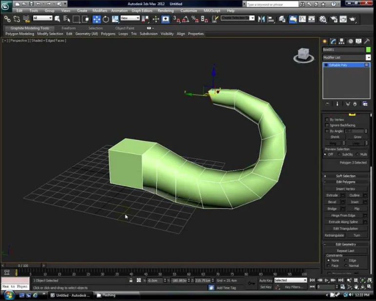
The easiest, cleanest way to build your main structure is by using Splines (2D lines) and extruding them upward:
- Trace the Blueprint: Go to your top viewport, select the Line tool, and make sure your vertex snaps are turned on. Click your way around the perimeter of your blueprint walls to create a closed, continuous 2D outline of the floor plan.
- Apply the Extrude Modifier: Once you have a closed 2D shape of your walls, head over to your modifier list on the right panel and select Extrude. Type in your real-world wall height in the parameters box for example, 270 cm or 3 meters). Instantly, your flat lines pop up into perfect, clean 3D walls.
- Cap the Floor and Ceiling: To create your floor and ceiling, you don’t need to draw anything new from scratch. Just make a copy of the flat spline you used for the walls, remove the wall thickness lines, and apply a flat plane or a tiny extrusion to act as your solid flooring. Move another copy to the very top of your walls to seal the room as your ceiling.
By building your outer shell as a single, perfectly sealed unit, you completely prevent light from leaking through the corners of your room when you start rendering later. It keeps your project incredibly lightweight and gives you a solid foundation for the next steps.
Step 2: Cutting Openings for Doors and Windows
Now that you have a solid, continuous outer shell, you need to put holes in it for your doors and windows.If you look up basic tutorials for this step, a lot of them will tell you to use a tool called “ProBoolean” which basically means drawing a 3D box where the window should be and using the software to stamp a hole through the wall.
To keep your walls perfectly clean and professional, the best workflow is to use the Edit Poly method:
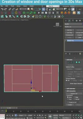
- Add an Edit Poly Modifier: Select your extruded walls, go to your modifier list, and drop an Edit Poly modifier right on top of the stack. This lets you manipulate the actual faces and edges of your 3D walls.
- Slice Your Heights: Switch to Edge Mode and select the vertical edges of your walls. Use the Connect tool to create two horizontal lines all the way around your room. Move the bottom line to your exact window sill height (like 90 cm) and the top line to your window header height (like 220 cm).
- Bridge the Openings: Switch to Polygon Mode (faces). Select the square polygon on the inside wall where the window goes, and hold control to select the matching square polygon on the outside wall. Click the Bridge button. Instantly, the software punches a perfect, clean opening through the wall and seals the inside edges automatically.
Step 3: Importing and Positioning Architectural Elements
With your structural shell ready and your window holes cleanly punched out, it is time to bring in your actual architectural components. This includes things like your window frames, glass panes, door assemblies, baseboards, and crown molding.
A massive pitfall for beginners here is using the basic “Open” command or trying to drag and drop files directly into the active viewport. Doing this can accidentally overwrite your workspace settings, mess up your carefully calibrated units, or cause the software to instantly crash if the asset was saved in an older or corrupted format.
To keep your main project completely stable, follow this clean import routine:
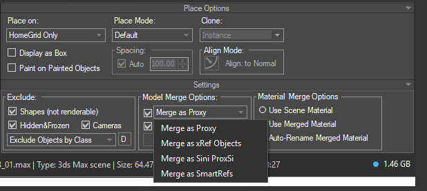
- Always Use the Merge Command: Never open an asset file directly. Instead, go to File > Import > Merge. This safely brings the 3D geometry of your doors or windows into your existing scene without altering your workspace setup or system preferences.
- Verify the Asset Scale Immediately: Even if you downloaded a high-quality model from a reputable source, it might have been built using different units (like inches instead of centimeters). The moment you merge an object, check its size against your walls. If a door frame shows up as small as a coffee cup or as big as a house, use the Uniform Scale tool to resize it to real-world measurements right away.
- Use Instances for Repeating Objects: If your design features ten identical windows across a facade, do not make standard copies of them. When duplicating your merged window, choose Instance instead of Copy in the options menu. This tells the software to share the data geometry. If you decide to change the frame color or tweak the hardware later, updating just one instance will automatically update all ten, saving you hours of tedious backtracking while keeping your file size tiny.
Step 4: Setting Up Cameras and Locking Visual Angles
Before you start adding furniture, choosing fabrics, or setting up complex lighting, you need to place your cameras.A massive trap that almost every beginner falls into is modeling an entire room from top to bottom before setting up a shot. This wastes days of work. By framing your camera views early, you know exactly what will be visible in the final image. If the camera can’t see a specific corner of the room, you don’t need to waste time detailing it, adding crown molding there, or optimizing its geometry.
To set up a composition that looks like professional architectural photography rather than a video game screenshot, follow this workflow:
- Use a Physical Camera: Go to your command panel, click Create > Cameras, and choose Physical Camera. Click and drag in your top viewport to place the camera body in the room, pointing the target toward your main focal point (like a fireplace or a large window).
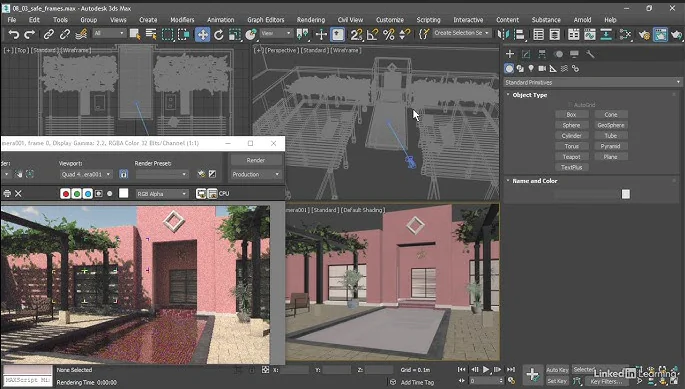
- Turn on Safe Frames (Shift + F): This is the most crucial shortcut for composition. Pressing Shift + F places a bright border around your active viewport, showing you the exact crop ratio of your final render. Without Safe Frames turned on, what you see on your screen is just a random guess based on how big your monitor is, which leads to chopped-off ceilings or floors when you click render.
- Match Real-World Architectural Lenses: Select your camera and open the Modify panel. For interior architecture, set your focal length between 24mm and 35mm. Anything wider than 24mm creates a “fish-eye” effect that stretches the walls distorting the space like a funhouse mirror. For tight, stylized close-ups of furniture or decor, swap to a 50mm or 85mm lens.
- Enable 2-Point Perspective: In the camera settings, always check the box for Auto Vertical Tilt Correction. In professional architectural photography, vertical lines (like the corners of walls or door frames) must always run perfectly straight up and down. If your camera is tilted slightly upward to see the ceiling, the walls will look like they are falling backward. This single click fixes that instantly.
Step 5: Master the Basic Lighting Environment
Once your camera angle is locked down, you need to establish your lighting foundation. In architectural visualization, you should always handle your lighting before you start applying colors or textures to your furniture. If you try to mix materials and lighting at the same time, you won’t know if a wall looks too dark because of its texture or because your scene simply doesn’t have enough light.
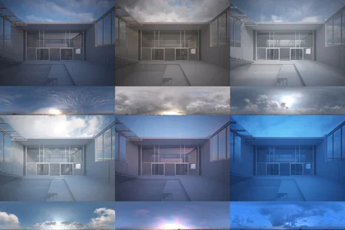
Add a Physical Sun and Sky: Go to your creation panel under Lights, choose your render engine’s daylight tool (like Chaos Corona Sun or V-Ray Sun), and click and drag in your top viewport to place it. Position the sun object outside your building, aiming the target directly through your main windows. The software will automatically ask if you want to add a matching Sky Environment map and always click yes. This links the sky’s brightness and color directly to the angle of your sun.
Dial in the Sun Height for Mood: The altitude of your sun completely changes the story your image tells. If you place the sun high in the sky, you get bright, crisp, high-contrast daylight with short, sharp shadows. If you lower the sun close to the horizon line, you instantly get a warm, golden hour or twilight effect with long, soft shadows stretching across the room.
Use Light Portals for Crisp Interiors: If you are rendering an indoor room and the scene looks incredibly dark or grainy, don’t just crank up the sun’s brightness until the windows turn completely white. Instead, place flat Portal Lights directly outside the window openings, matching the size of the glass. Portals act like funnels, gathering the ambient blue light from the outdoor sky map and pushing it deep into the dark corners of your room without creating ugly rendering noise.
Step 6: Smart Material Application and PBR Texturing
Now that your room is beautifully lit in a neutral gray clay state, it’s time to replace those flat gray surfaces with realistic materials like wood, concrete, glass, and fabrics.
To keep your materials organized and perfectly scaled without lagging your machine, stick to this professional texturing workflow:
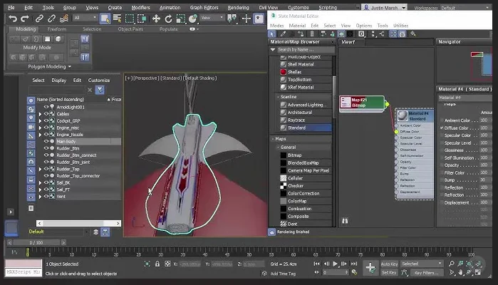
- Use the Slate Material Editor: Press M on your keyboard to open your material settings and make sure you are using the Slate Material Editor view rather than the old compact view. The Slate editor works like a visual flowchart, allowing you to drag, drop, and wire your color maps and bump maps together cleanly so you can see exactly how complex multi-layered materials are constructed.
- Lock In Real-World Map Size: A classic beginner mistake is applying a wood texture to a floor and spending twenty minutes guessing the tiling numbers until it looks “okay.” Instead, check the box for Use Real-World Scale inside your texture coordinates. Then, apply a UVW Map modifier to your object and set it to Real-World Map Size. If your wood texture is designed to be exactly 200 cm wide in real life, you simply type “200 cm” into the settings, and the software scales it perfectly across your floor automatically.
- Break Up Obvious Tiling Patterns: If you are texturing a massive concrete wall or a large hardwood floor, standard textures will repeat over and over, creating an ugly, artificial checkerboard pattern across your room. To fix this, use a UVWRandomizer or a multi-texture map node. This subtly shifts, rotates, and randomizes the position of the texture across different planks or panels, creating the natural, imperfect variations you see in real-world materials.
Step 7: Final Render Optimization and Output Settings
You’ve built the walls, punched out the windows, framed your shot, lit the space, and applied realistic textures. Now comes the final hurdle: baking all that hard work into a crisp, photorealistic image.
The biggest pitfall for beginners here is blindly cranking all the quality sliders to maximum and hitting “Render.” This is a massive mistake that will either cause your software to crash from running out of memory, or leave you waiting 12 hours for a single frame to finish. Professional architectural visualization is all about rendering smarter, not harder. You want print-ready quality without melting your computer.
To get clean, lightning-fast final outputs, use this optimization routine:
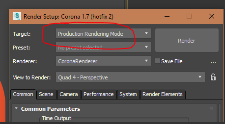
- Lock in Your Frame Size (F10): Press F10 to open your Render Setup menu. Under the Common tab, head to the Output Size section. Ensure your aspect ratio matches the exact camera Safe Frames you locked in earlier. For quick client previews or portfolio sites, a width of 2000 to 3000 pixels is plenty. Only jump up to 4K or higher if you are printing a massive physical banner for a construction site.
- Set a Strict Noise Limit: Instead of letting the software calculate light bounces forever, tell it exactly when to stop. In modern render engines (like Chaos Corona or V-Ray), go to your performance settings and set a Noise Level Limit of around 2% to 3% for your final production renders. Anything lower than 2% is practically invisible to the human eye but will double your rendering time.
- Let the Denoiser Do the Heavy Lifting: Do not wait for the render engine to clean up every single speck of grain naturally. Turn on an advanced denoiser (like the Corona High Quality Denoiser or V-Ray Denoiser). The engine will stop rendering once it hits your 3% noise limit, and the denoiser will instantly smooth away any remaining grain in a couple of seconds. This single trick cuts your total rendering time straight in half.
- Save in a Flexible, High-Dynamic Format: Never save your raw final render as a standard JPEG. JPEGs compress your image and destroy the subtle light gradients. Instead, save your file as a 16-bit TIFF or a .EXR file. These formats preserve all the deep exposure and shadow data, meaning if your highlights look a little blown out near the windows, you can easily pull those details back down in Photoshop later without ruining the image quality.
Critical Modeling Techniques for Clean Scene Management
While following the seven-step pipeline guarantees a beautiful final image, your long-term success with 3ds max architectural modeling comes down to how clean and editable your project file remains when sudden design changes happen. Instead of smashing permanent 3D shapes together like building blocks which creates messy geometry and rendering errors, professional workflows rely on spline-based construction by tracing clean 2D footprints over blueprints and extruding them upward.
By keeping your modifier stack intact and using modern, non-destructive tools like Smart Extrude, your entire project stays completely flexible, allowing you to effortlessly shift walls or cut new openings later without ever having to rebuild your assets from scratch.
Common Pitfalls: Why Your Scene is Lagging or Crashing
A lagging viewport or a sudden software crash can instantly ruin your workflow. If 3ds Max is running slow, it usually comes down to three simple things you need to fix:
- Heavy Poly Counts: Importing highly detailed furniture models from online libraries is great, but a single unoptimized asset like a decorative plant or cushion can freeze your screen. Use Proxies for heavy, repeating objects to keep your viewports lightning-fast while retaining full rendering detail.
- Unoptimized Textures: Running dozens of massive, uncompressed 8K textures will quickly crush your computer’s memory. Stick to 2K or 4K textures for background objects and minor details. Your file will load much faster, and the final render quality will look exactly the same.
- Overloaded Modifier Stacks: Leaving hundreds of active modifiers running across your scene forces the software to constantly recalculate data in the background. Once you are completely happy with a wall, window frame, or piece of furniture, right-click and collapse the stack to an Editable Poly to instantly clear your system memory.
Conclusion
A well-organized scene setup in Autodesk 3ds Max makes architectural visualization faster, cleaner, and more realistic. By using the right workflow for modeling, lighting, materials, and rendering, beginners can avoid common mistakes and create professional-quality results more efficiently. With regular practice, these techniques will help you build smoother workflows and better architectural renders in 3ds Max.