How to use SOLIDWORKS for 3D printing?
We all know that designers and engineers are inclined towards 3D modeling these days since it reduces design time and expenses. The ability to review, test, and update each component of a structure or product before manufacturing is provided by 3D CAD software. You avoid having to start over from scratch by doing this. These are the main reasons due to why the world is moving towards 3D modeling.
Well, you can find a number of 3D design software, however, in this blog, we will discuss SOLIDWORKS. So without further ado, let’s go and find out what is SOLID WORKS and how we can perform 3D printing with it.
What is 3D modeling?
A 3D computer graphics method known as “3D modeling” entails creating a virtual mathematical representation of any real-world item in three dimensions within a computer-based simulation using specialized modeling software.
A 3D model is the result of 3D modeling, and models can be made manually or automatically. Video games, film, architecture, art, engineering, and commercial advertising are just a few of the media that use 3D models. Character animation and special effects require the ability to completely animate digital objects, which is only possible with 3D modeling.
What is SOLIDWORKS?
Engineers and designers use SOLIDWORKS 3D CAD software frequently during the design development phase. With the capacity to run the concept design through many scenarios and make revisions as necessary in the design development process, SOLIDWORKS 3D models are turning ideas into reality.
The designer can import and translate data, as well as safely store it and maintain its adaptability and accessibility, using the SOLIDWORKS 3D CAD program. Users can quickly create 3D models from 2D data by importing 2D data into SOLIDWORKS in the DXF, DWG, and AutoCAD Sections formats. Drawing parts from DWG files can be dropped into 3D SOLIDWORKS models using the Design Clipart tool, and View Folding automates the creation of 3D models by changing the features of an imported 2D drawing.
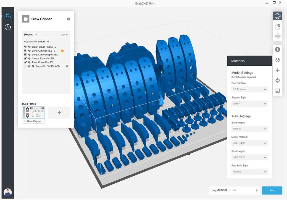
3D Printing with SOLIDWORKS
Step 1: Modeling at a correct and closed volume
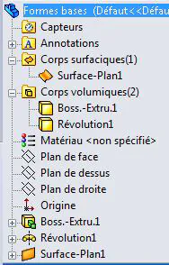
Solid and Surface modeling are the two primary forms available in SolidWorks. The program refers to each object as a body. Within SolidWorks, a body can be produced using one of the two modeling techniques or by joining two already-existing bodies.
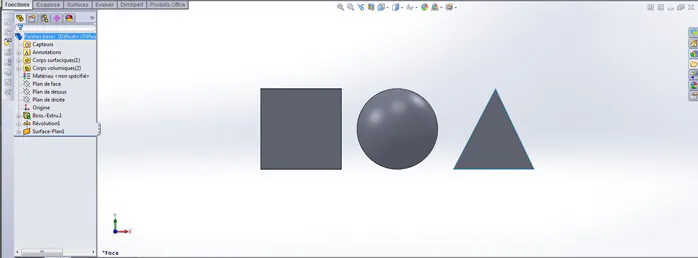
At the top of the scroll-down menu on the left side of the interface, you can view the total number of solid and surface bodies.
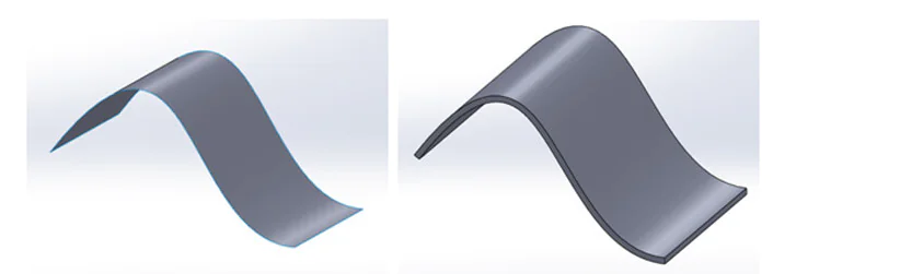
When building vehicle bodies, waves, or other specialized forms, surface modeling offers significant advantages. But it’s preferable to output a file with solely solid bodies for a 3D print. This is because surface bodies cannot be transformed into physical forms since they lack a recorded virtual weight. For the printer to properly apply the information, your 3D model must have a minimum weight that matches the restrictions of the material that will be utilized.
Let’s start by only working with solid bodies.
Step 2: Understanding solid modeling
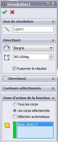
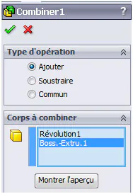
Check the “Merge Result” option in the scroll-down menu that displays the function, then check “Selected Bodies” to create a file in solid modeling mode with a single body.
It is always feasible to combine several bodies with SolidWorks’ boolean tool if you are not able to pick this option when running the function or if you would rather not merge the bodies right away. This tool may be found under Insertion>Functions>Combine; utilize the “Add” option to combine multiple solid bodies into a single one.
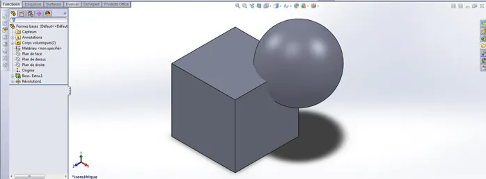
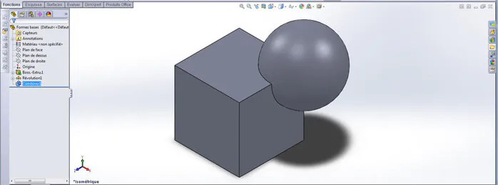
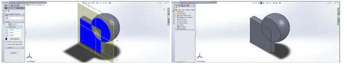
Every function used in SolidWorks creates a volume that complies with 3D printing requirements, given that they match the predicted print material. When examining a cut view, you may determine whether or not your model is completely integrated. Whereas intersecting bodies will not result in a blue solid, merging bodies will.
Note: The cut piece of the items in the two images below causes a gap in the blue coloring since the bodies are not merged or joined.
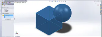
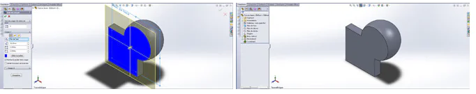
A cut part of the two bodies generates a solid color of blue after using the “Combine” tool, indicating that the bodies are properly merged.
For your 3D print, we strongly advise sticking to solid functions solely if your design can be produced without surface functions. Extruded boss/base, revolved boss/base, swept boss/base, and loft boss/base are among the functions that are mostly the same in both types. However, if necessary, surface functions can be used.
Step 3: Understanding surface modeling
Before exporting, it must be transformed into a solid to provide a printable surface model. Consequently, it’s crucial to remember that the surface bodies you construct will eventually become solid entities. Your surface bodies should be closed with common, continuous, and finite borders to do this. Alternatively, it needs to be waterproof. This makes it simple to transform the surface “skin” into a solid body.
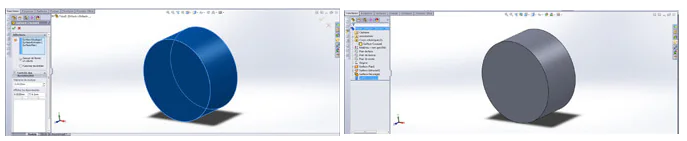
A different choice is to employ the “Thicken” tool, which enables you to identify the thickness of both your surface and the actual print. If you want to use this option, remember the minimal specifications for the printing medium you want to use.
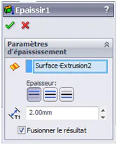
Additionally, keep in mind that the “Thicken” option is accessible from the “Boss/base” menu, which is typically linked to solid features. By completing this challenge, your object will become a solid body.
Step 4: Hollow your model
For 3D printing, making a hollow model is crucial since it reduces the quantity of material needed to make the thing. The cost of production will be significantly reduced if the item is hollow, and some materials need a certain size to print well.
Direct hollowing of an object is possible in SolidWorks using the “Shell” function. However, remember that you will need to decide on the surface you will use for your draining hole and the wall thickness.

Not every component must be hollowed out. More delicate sections, however, shouldn’t always be hollowed out. And in other instances, fundamental engineering principles can preserve structural strength while reducing the total amount of material required.
Note: Make sure to leave a hole to allow extra material to drain if you choose the “Hollow” function without choosing a face to allow the item to empty. The object will be perceived as a solid object and will be printed and priced as such if there isn’t a hole to let the extra material drain through.
Step 5: Understanding relief texts and motifs
You have two options if you want to include text on your model:
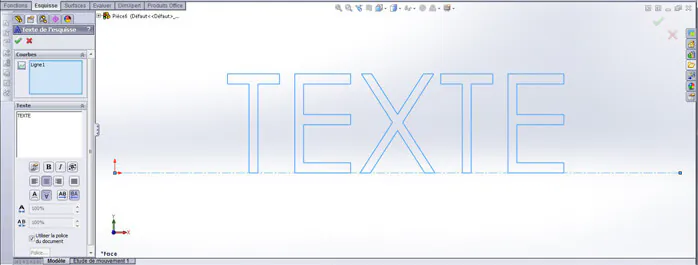
Use the SolidWorks text tool.
Import a text or image that already exists.
When using the text tool in SolidWorks, you must first choose the text’s orientation before you can add text and adjust the typography as necessary. The outline can then be used like any other sketch in the software and given functionalities.
Step 6: Understanding moving and assembled pieces
You can produce moving and articulated parts with 3D printing in a single step. There are a few guidelines that must be followed in order for your piece to come out correctly, but it can be fully constructed and used right out of the printer.
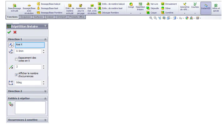
For instance, a plastic component needs a 0.5 mm space between surfaces. If not, the pieces will be fused together by the heat produced during printing. Using SolidWorks tools will be very helpful for measuring items’ distances precisely.
1 Smart Dimension
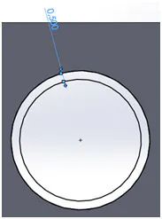
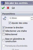
2 Offset entities
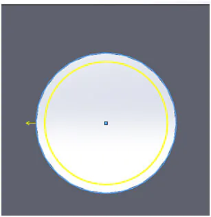
3 Linear or circular pattern
Step 7: Coloring and Texturing for a multicolored 3D print
A mechanism for setting up the model for various materials that can be merged into 3D is available in SolidWorks (photo view 360). However, the produced colors and materials cannot be exported. A SolidWorks file with textures cannot be directly exported.
Conclusion
An essential component of many creative jobs is 3D modeling. It helps engineers and architects plan and design their projects. 3D modeling is a crucial tool for animators and game designers. Additionally, 3D modeling is used in almost every blockbuster movie for special effects, cost-savings, and production speed.
Millions of engineers and designers at tens of thousands of businesses use SOLIDWORKS. It is among the most widely used design and engineering programs available for 3D modeling. SOLIDWORKS is utilized by many different professions and businesses all over the world because of its wide range of features and excellent functionality.
The use of parametric design in SOLIDWORKS makes it a powerful tool for designers and engineers. As a result, the designer can observe how adjustments would impact nearby components or even the entire solution. Increased component size, for instance, would have an impact on the joint or hole it is linked to. This makes it simple and quick for designers to identify and fix problems.