How to Start Node-Based Character Rigging with Bone Info Nodes & Python Drivers in Blender
You’ve spent hours setting up a character rig: bones are placed, weights are painted, and everything looks fine until the animator moves an arm and the shoulder collapses, the forearm doesn’t twist, and the fingers refuse to curl naturally. You fix one thing, and something else breaks.
Traditional Blender rigging relies heavily on stacking bone constraints. Every new character requires the same setup rebuilt from scratch. You cannot reuse logic or automate repetitive bone relationships. Debugging a deep chain of 20 constraints feels like pulling wires in the dark.
But with Bone Info Nodes and Python Drivers, rigs stop being collections of manually connected constraints. They become intelligent systems where bones communicate through logic: one master control can drive an entire hand, and shaders can react to bone poses in real-time.
This method works for both beginners and advanced riggers. Beginners can start with simple expressions and scale gradually. Experts can build full production-ready characters without the rig breaking down.
Step 1: Armature Setup
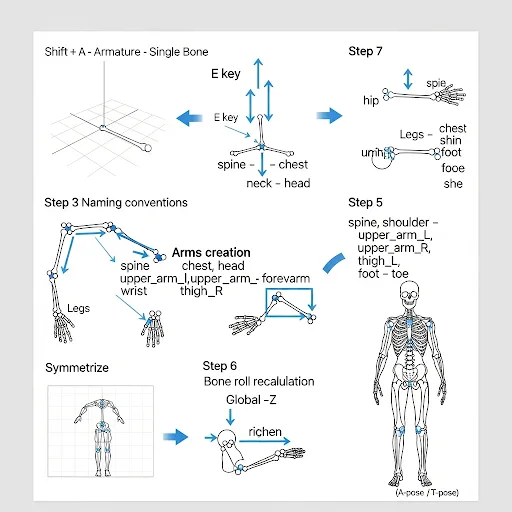
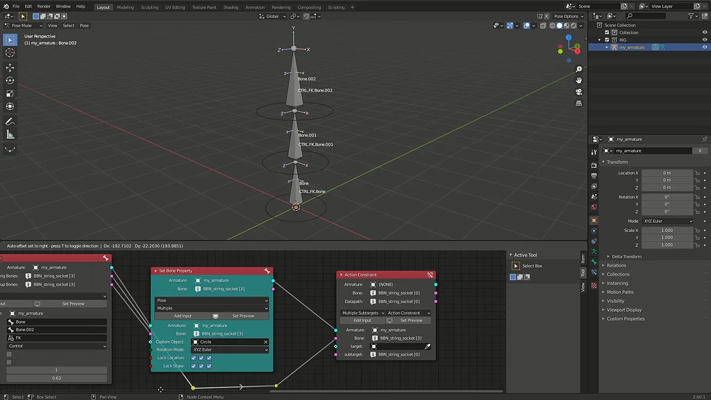
Start by adding a single bone to your scene: press Shift + A → Armature → Single Bone and enter Edit Mode. Extrude bones to create your chains by selecting the tip of a bone and pressing E, forming your spine from hip → spine → chest → neck → head, arms from shoulder → upper arm → forearm → wrist, and legs from thigh → shin → foot → toe. Name each bone clearly using lowercase with underscores, adding _L or _R for left and right sides, then use Armature → Symmetrize to mirror the bones automatically. Select all bones and recalculate the bone roll by going to Armature → Bones → Recalculate Roll → Global -Z to align orientations consistently. Position your character in a natural A-pose or T-pose and exit Edit Mode to set it as the rest pose. Optionally, assign custom bone shapes by selecting a bone, opening Bone Properties → Viewport Display → Custom Object, and choosing a shape like a circle or diamond to make your rig easier to select in Pose Mode.
Step 2: Pose Mode Basics
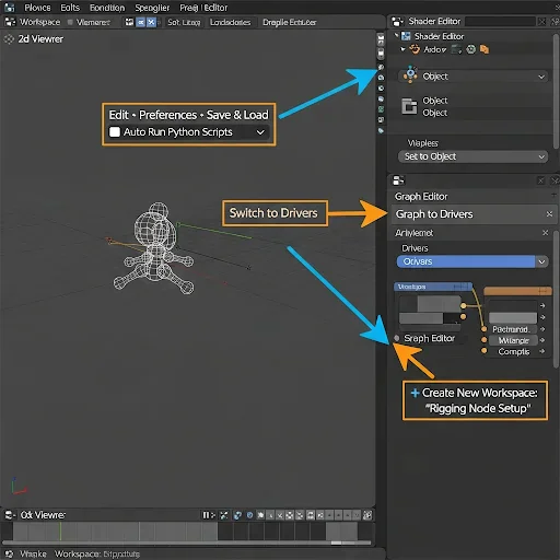
Enable Python scripts so your drivers work without errors. Go to Edit → Preferences → Save & Load and turn on Auto Run Python Scripts. This ensures every Python driver you create runs automatically in the viewport. Next, split your Blender workspace into three panels: keep the 3D Viewport on the left, open the Shader Editor on the top right, and the Graph Editor on the bottom right. In the Graph Editor, switch the top-left dropdown from F-Curve to Drivers to focus only on driver data. In the Shader Editor, set the dropdown to Object so your material stays active. Save this layout as a custom workspace by clicking the + next to the workspace tabs and naming it, for example, “Rigging Node Setup.” Finally, create a clean rigging file containing only the mesh, armature, and a basic material; avoid lights, cameras, or complex scenes to ensure driver updates stay fast and responsive.
Step 3: Bone Info Node Setup
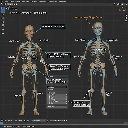
Add your armature and prepare bones for node-driven rigging. Press Shift + A → Armature → Single Bone in the 3D viewport to create your starting bone at the scene center. Immediately press Tab to enter Edit Mode—never add bones in Pose Mode, as it creates offset transforms that break driver values. Extrude new bones from the root using E to maintain proper parent-child relationships. Build your chains logically: spine flows Hip → Spine → Chest → Neck → Head; arms branch Shoulder → Upper Arm → Forearm → Wrist; legs flow Hip → Thigh → Shin → Foot → Toe. Keep each chain connected through extrusion so Blender correctly registers hierarchy. Rename every bone in the Item panel using lowercase letters and underscores, e.g., upper_arm_L, spine_01; avoid spaces, dots, or special characters. For symmetrical rigs, add _L and _R suffixes, then use Armature → Symmetrize to mirror bones automatically. Check Bone Roll by selecting all bones and going Armature → Bones → Recalculate Roll → Global -Z Axis; this ensures local axes align correctly, preventing rotation errors when writing drivers. Finally, set your rest pose in a natural A-Pose or T-Pose—this zero baseline ensures all subsequent driver calculations.
Step 4: Set Up Pose Mode & Understand Bone Transforms
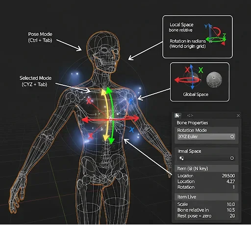
After building your bone chains and setting the rest pose, enter Pose Mode by selecting your armature and pressing Ctrl + Tab. This is where all driver inputs will live, so get familiar with how Blender tracks Location, Rotation, and Scale for each bone. Rotate, move, and scale bones while watching the Item panel (N key) to see real-time transform values. Remember, rotation values are in radians, not degrees, and the rest pose always equals zero.
Decide whether each driver should read Local Space (relative to the parent bone, most common for character rigs) or Global Space (relative to the world origin, used only for scene-relative effects). Switch your controller bones’ rotation mode to XYZ Euler under the Bone Properties panel to simplify driver calculations and avoid quaternion complexity. By practicing live bone transforms in Pose Mode, you’ll know exactly what input values each driver receives, preventing miscalculations and making your Python expressions predictable.
Step 5: Add Drivers and Set Variables
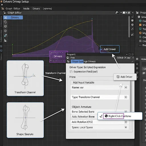
After learning how bone transforms work in Pose Mode, you are ready to add drivers to automate your rig. Right-click on any numeric property you want to control such as a bone’s rotation, a shape key value, or a material input, and select Add Driver. The property turns purple, showing it is now driven. Open the Graph Editor, switch to Drivers mode, and select your driver. Press N to open the sidebar, set the Driver Type to Scripted Expression, and add a variable by clicking Add Input Variable.
Name it var and choose the type depending on your source: Transform Channel to read bone transforms, Single Property for custom controls, Rotational Difference for corrective angles, or Distance for object separation. For a Transform Channel, assign your armature as the object, select the exact bone, choose the correct rotation or location axis, and set the space to Local Space. Finally, type var in the expression field to pass the value directly to the driven property. Move the source bone to confirm the target reacts correctly, then refine the expression by multiplying, inverting, or offsetting the value to achieve precise Control.
Step 6: Python Expressions in Drivers
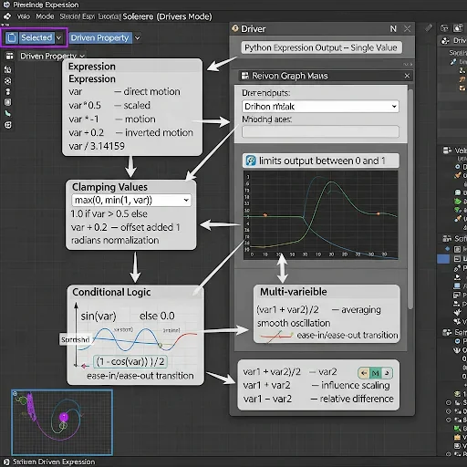
With your driver set up, you can now write Python expressions to control behavior dynamically. The expression field evaluates whatever you type and outputs a single number to drive the property. Start simple: typing var passes the input directly, while var * 0.5 halves it, and var * -1 inverts the motion. Use var + 0.2 to add an offset or var / 3.14159 to normalize radians for shape keys or material inputs. To prevent unwanted values, clamp expressions like max(0, min(1, var)) keep outputs within safe limits. For conditional behavior, use expressions like 1.0 if var > 0.5 else 0.0 to trigger actions when a bone passes a threshold, ideal for IK/FK switches. Trigonometry adds natural motion: sin(var) produces smooth oscillations, and (1 – cos(var)) / 2 converts linear rotations into eased transitions. You can also combine multiple variables: add var1 and var2 to average rotations, multiply them for influence scaling, or subtract them to measure relative angles. Always test expressions live in Pose Mode, moving bones and reading values in the N Sidebar, so your math matches actual motion, and your rig stays predictable.
Step 7: Bone Info Node
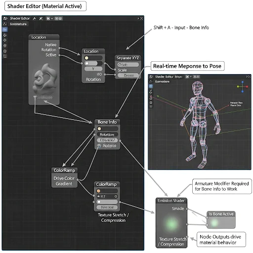
Open the Shader Editor with your character mesh selected and its material active. Press Shift + A > Input > Bone Info to add a Bone Info Node to your node tree. This node gives direct access to the selected bone’s position, rotation, scale, and selection state. Connect the outputs to Separate XYZ or Math nodes to isolate and manipulate individual axes. For example, use the Location output to drive color gradients or map bone positions to material effects.
Use Is Bone Active to trigger emission highlights on mesh regions when the animator selects a bone, and use the Scale output to stretch or compress textures dynamically as bones scale. Always verify that the armature modifier is active on your mesh; the Bone Info Node will not detect bone data. By testing each output in real time, you ensure that your material reacts immediately to pose changes and supports your procedural rig logic seamlessly.
Step 8: Python Driver & Bone Transform
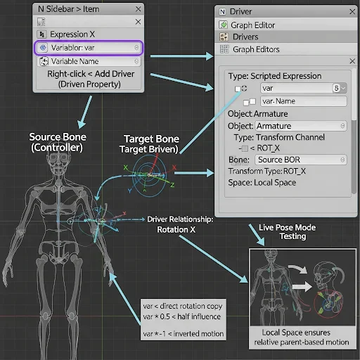
Enter Pose Mode with your armature selected and identify your source bone (the one the animator will move) and your target bone (the one that should react automatically). Right-click the Rotation X field of the target bone in the N Sidebar > Item panel and select Add Driver. The field turns purple, indicating the driver is active. Open the Graph Editor, switch to Drivers mode, and select your new driver. In the driver sidebar, set the Type to Scripted Expression. Under Variables, create a new variable of type Transform Channel, set Object to your armature, select the exact source bone, set Type to ROT_X, and Space to Local Space. In the expression field, type var to directly pass the rotation from the source to the target. Move the source bone to verify that the target mirrors its rotation. Modify the expression to var * 0.5 for a half-speed response or var * -1 for inverted motion. By following this workflow, you establish the core Python-driven rig logic, enabling one bone to control another with precision and making all subsequent driver setups scalable and reusable.
Step 9: One Bone Driving Multiple Bones
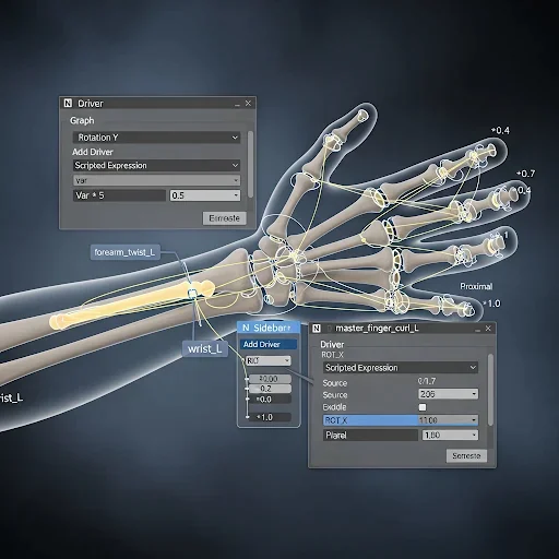
Add a dedicated twist bone inside your forearm, for example, forearm_twist_L, to handle forearm rotation. Enter Pose Mode, right-click the Rotation Y field of this twist bone in the N Sidebar > Item panel, and select Add Driver. Open the Graph Editor, switch to Drivers mode, and select the new driver. Set the Type to Scripted Expression. Under Variables, choose Transform Channel, set the Object to your armature, select the wrist_L bone as the source, set Type to ROT_Y, and Space to Local Space. In the expression field, type var * 0.5 so the twist bone rotates at half the wrist’s speed. Test by rotating the wrist; the forearm twist should follow smoothly. To extend this system, add a master control bone like master_finger_curl_L near the hand. For each finger joint, add drivers on their Rotation X fields, set variables to read the master bone’s ROT_X, and use incremental multipliers (var * 0.4, var * 0.7, var * 1.0) for proximal, middle, and distal joints. Copy this driver setup across all fingers, updating only the target bones while keeping the variable and expression consistent. This workflow lets one control bone animation multiple bones simultaneously, creating natural, scalable finger and forearm motion without manually adjusting each joint.
Step 10: Custom Properties as Driver Controllers
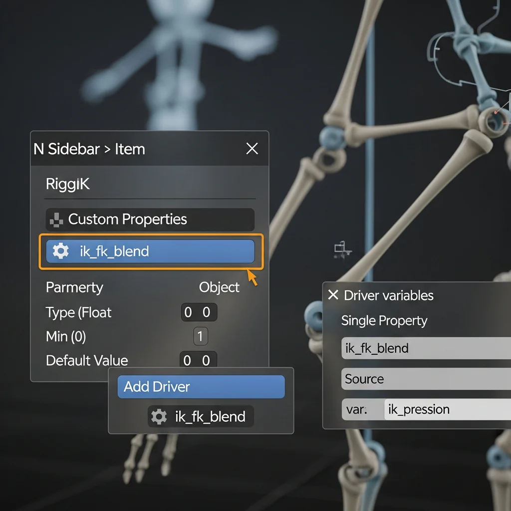
Select your master control bone in Pose Mode and open the N Sidebar > Item panel. Scroll down to Custom Properties and click New to create a property. Click the gear icon to set the Type (Float for sliders, Boolean for on/off switches), name it descriptively, e.g., ik_fk_blend, and set Min to 0, Max to 1, with a default value. Right-click any property you want to control, such as an IK constraint influence, and select Add Driver. In the driver Variables, choose Single Property, set the Object to your armature, and pick your custom property as the source.
Type var in the expression field to directly pass the slider value to the driver. Test by moving the slider; the IK/FK influence changes smoothly. Repeat this process for FK bones, using var or 1 – var in the expression to ensure the switch behaves correctly. This method turns your rig into a clean, animator-friendly system, letting one slider control complex behaviors across multiple bones without manually adjusting drivers or constraints.
Step 11: Shape Keys & Python Driver
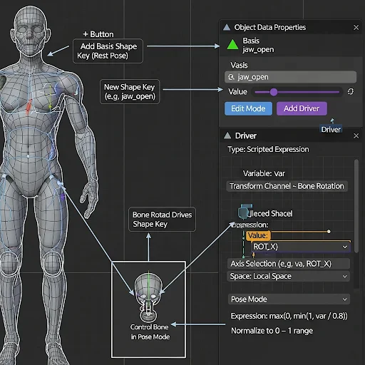
Select your character mesh and open the Object Data Properties panel (green triangle icon). In the Shape Keys section, click + to add the Basis shape key as the rest pose. Click + again to create a new shape key and rename it descriptively, e.g., jaw_open or brow_raise_L. Enter Edit Mode, sculpt the target shape for the desired deformation, and exit Edit Mode. Right-click the Value field of your shape key and select Add Driver.
Set the driver variable to read the rotation of the controlling bone, choose the appropriate axis, and enter a Python expression like max(0, min(1, var / 0.8)) to map the bone rotation to a normalized 0–1 range. Test by rotating the bone in Pose Mode; the shape key should respond automatically. For corrective shapes, create a new shape key, sculpt the corrected mesh, add a driver using the Rotational Difference between two bones (e.g., upper arm and forearm), and normalize the expression to match the maximum rotation. This ensures elbows, shoulders, and other joints deform naturally without manual keyframing.
Step 12: Geometry Node
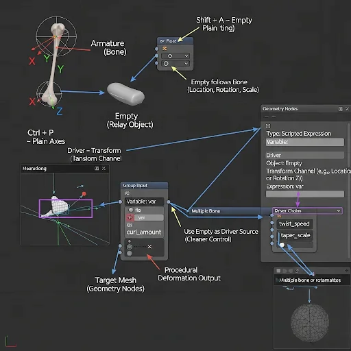
Add an Empty object via Shift+A > Empty > Plain Axes. In Object Mode, select the Empty, then Shift-select your armature and enter Pose Mode. Select the bone you want to track, press Ctrl+P, and choose Bone from the parenting menu. The Empty now follows the bone’s position, rotation, and scale in real time. Open your Geometry Nodes modifier on the target object and add a Group Input float parameter, e.g., curl_amount. Right-click the input field, choose Add Driver, and set the driver variable to read the Transform Channel of the Empty, not the armature.
This creates a clean relay: the bone drives the Empty, and the Empty drives the Geometry Nodes input. Repeat for multiple bones to drive other parameters like twist_speed or taper_scale. Test in Pose Mode, rotating or moving the bones, should immediately update the procedural deformation in Geometry Nodes, giving full control over curves, tentacles, or any rigged procedural mesh.
Debugging & Common Errors
Fix Circular Dependency
If a driver freezes because Bone A drives Bone B and Bone B drives Bone A, identify the loop in your driver chain. Break the circular reference by removing one driver and replacing it with a Copy Rotation or Copy Location constraint. This lets Blender calculate bone transforms correctly without conflicting dependencies.
Refresh Drivers
When a driver does not update in the viewport, press Ctrl+Alt+F to force all drivers to recalculate. Ensure Auto Run Python Scripts is enabled under Edit > Preferences > Save & Load. Verify that the driver variable references the correct bone and uses the correct Local Space or Global Space.
Enable Python Scripts
If the driver expression shows zero or an error, open Edit > Preferences > Save & Load and confirm Auto Run Python Scripts is ON. Check your expression for syntax errors; missing parentheses, wrong operators, or misspelled functions are common issues. Test the expression by replacing it temporarily with var to confirm the variable works.
Correct Axis Issues
When a driver reacts in the wrong direction, check your bone roll in Edit Mode. Recalculate roll using Armature > Bones > Recalculate Roll > Global -Z Axis. Verify the driver variable reads the correct axis corresponding to your intended motion.
Fix Bone Name Errors
If Blender raises a KeyError, open Edit Mode and copy the exact bone name from the Item panel. Replace any spaces with underscores and update all driver references. Names must match exactly. Python is case-sensitive and space-sensitive.
Resolve Unexpected Driver Values
When a driver outputs incorrect values, first check the Space setting in the variable switching between Local and Global Space can fix mismatched outputs. Verify your expression math, and confirm the rotation mode is Euler XYZ, not Quaternion, to avoid confusing values. Make small test poses and read the rotation values in the N sidebar to ensure correct mapping.
Full Character Rig Walkthrough
Build Spine with Auto-Follow
Start by creating your spine chain: Hip → Spine_01 → Spine_02 → Chest. Enter Pose Mode, select Spine_01, right-click its Rotation Y and Rotation Z fields, and choose Add Driver. In the driver sidebar, set Type to Scripted Expression and add a variable reading Hip bone ROT_Y and ROT_Z in Local Space. Set the expression to var * 0.3 for Spine_01, var * 0.2 for Spine_02, and var * 0.1 for Chest. Now, rotating the hip drives the spine with diminishing influence, creating natural motion without additional constraints.
Add Forearm Twist and Shoulder Correction
Insert a forearm_twist_L bone along the forearm. Add a driver reading wrist ROT_Y in Local Space and use the expression var * 0.5. This ensures the forearm twists proportionally to wrist rotation. For the shoulder, sculpt a corrective shape key named shoulder_raise_corrective_L. Add a driver reading upper_arm ROT_Z and map it with max(0, min(1, var / 1.2)). This maintains realistic shoulder volume when raising the arm.
Set up the Full Finger Curl System
Create a master_finger_curl_L control bone for the hand. Add drivers to all twelve finger joints using this master control: assign multipliers progressively (proximal 0.4, middle 0.7, distal 1.0) so fingers curl naturally. Repeat this pattern across all fingers, adjusting multipliers slightly for individuality. Test each finger in Pose Mode to confirm smooth, organic curling.
Implement Finger Spread Control
Add a second custom property on the master bone called finger_spread. Connect it via drivers to the Rotation Z of each finger’s proximal joint. Assign different multipliers to create realistic spreading: index 0.3, middle 0.1, ring 0.1, little finger 0.05. Now one slider controls both curl and spread interactively.
Wire IK/FK Switching
Set up IK on the arm, and FK controls separately. Add a driver to the IK Influence field and link it to a custom property ik_fk_blend. Use the expression 1 – var for IK influence and var for FK bones. Animators can now switch smoothly between IK and FK with a single slider.
Add Corrective Shape Keys
For elbows, shoulders, and knees, create corrective shape keys (e.g., elbow_bend_corrective_L). Add drivers using Rotational Difference between connected bones and map values with clamping expressions like max(0, min(1, var / 2.6)). These shape keys automatically correct mesh collapse during extreme poses.
Test Complete Rig
Pose your character in extreme positions: bend, twist, and spread limbs. Check spine follow, forearm twist, finger curl, IK/FK switching, and corrective shape keys. Adjust driver multipliers or bone roll if any motion behaves incorrectly. Repeat tests until the rig responds predictably under all poses.
Conclusion:
By now, you have a fully functional node-driven character rig where master controls, Python drivers, and Bone Info Nodes work together seamlessly. Test your rig by moving every control in extreme poses and verify that fingers curl, the spine follows naturally, forearms twist correctly, and corrective shape keys maintain mesh integrity. Your rig is procedural, non-destructive, and reusable across characters. Save a final version, document any custom properties, and share it with animators. They can now animate efficiently without breaking the underlying logic.