What is 3D Wireframe Modeling?
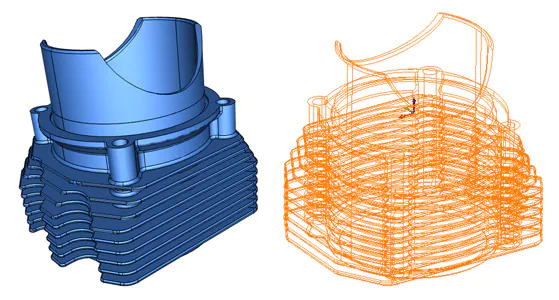
A 3D wireframe model is a skeletal representation of any real-world object. It proves beneficial to render any object model close to reality. It consists of various points, arcs, lines, circles, and curves to cleanly denote object edges and depth. The term “Wireframe” is derived from the origin when designers made use of metal wires to represent an object in three-dimensional space and shape. The 3D wireframe model is the abstract form of a 3D CAD model other two forms are surface modeling and solid modeling. These three modeling techniques when combined make up a well-defined realistic object model to demonstrate your concepts in real-time.
A wireframe model is created by roughly defining every edge and corner of the material object. The mathematical demonstration must be kept smooth for the two lines to merge into each other for a relatively clearer representation. The solid part is then aligned over the well combined skeletal representation like flesh over bones.
Advantages of 3D Wireframe Modeling
A few key advantages of 3D wireframe modeling include –
Elementary design creation and iterations for object assessment.
3D view of the created model from any perspective and angle.
It allows you to closely examine the object composition such as distances, perspective, potential differences, and corners, etc.
3D wireframe modeling helps automate orthographic and auxiliary views.
By utilizing this 3D modeling technique you can view reference geometry of a 3D solid, mesh, and surface modeling.
In places where a higher screen frame rate is desired many designers opt for 3D wireframe modeling and rendering techniques to keep things simple yet structurally perfect.
When a greater amount of graphical detail is needed, you can successfully add surface textures by using the 3D wireframe technique initially. All such possible practices allow designers to quickly create and evaluate solids or rotate an object within any desired position.
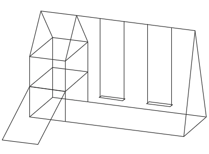
Wireframe models can be created by simple inputs from the designers hence it is not only effective but an easy task to pull off with the help of developing systems. One of the common techniques which are associated with 3D wireframe modeling is called “Extrusion”. In this technique, the 3D wireframe model is done by copying a 2D profile of the object and then extending it to a defined depth by the operator. Another technique is the rotation technique which requires rotation of cross-section of the profile of the object part about an axis.
Limitations
Like advantages, there are limitations of 3D wireframe modeling as well. A few of the challenges designers face while working with wireframe models. A designer faces a challenge to present inside and outside object surfaces. Generally, 3D models are quite complex but wireframe modeling makes things simpler enough for understanding any loopholes. Furthermore, it improves the object comprehensibility by enabling one dimension view.
You can make better use of a 3D wireframe model by –
Generating basic and simple 3D modeling designs can prove useful for timely evaluation and faster design iterations.
You can make better use of this technique by viewing your object model from any viewpoint.
Using the technique you can better analyze all object spatial relationships involving the distance between corners and edges to closely examine any existing potential interference.
You can generate better perspective views (except for Auto CADLT).
You can form standard auxiliary and orthographic views using the latest computer intelligent systems.
Also, the technique serves as a reference for 3D solid, surface, and mesh modeling layers.
Methods for Creating 3D Wireframe Models
Wireframe modeling techniques require rigorous experience and practice. The best way to learn to create new wireframe models is by beginning with simpler steps before attempting to directly pull off the model design.
You can effectively create a wireframe model by joining any 2D planar object within a 3D space. The method includes
Enter all 3D coordinates of the X, Y, Z locations appropriately to define points of the modeling object.
Set your desktop settings to the default work plane. Now join the X and Y planes of the UCS.
Now, you can move, copy or rotate these planes to move and rotate the entire object around.
Examples of 3D Wireframe Model
It is easier to begin your modeling journey with the 3D wireframe modeling technique. It proves useful to serve as reference geometry to align the object during surface and solid modeling phases. Let us consider a road that rises and makes a curve. The change will not be linear but curvy but with a constant radius like as illustrated below
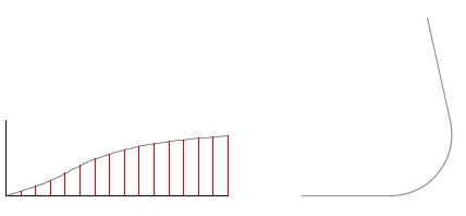
The T-shaped and equally spaced lines provide a good view of the outer and inner B-spine edge for the road model. The top of the T can be crowned.
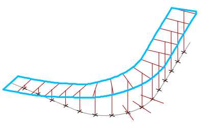
As you can notice from the above reference illustration the splines can be used to create rendering for a 3D solid object. Such type of modeling is suitable for cut, fill calculations, and structural engineering concepts.
Tips for Working with 3D Wireframe Models
The creation of a 3D wireframe model is difficult than the creation of a 2D orthographic view. Here are a few tips and tricks to help you deal with arising challenges during 3D wireframe modeling
Use isometric views to make a remarkable visualization model that allows easier object selection without any mistake.
Plan your modeling process and organize it in such a manner that you can turn off the layers to reduce the visual complexity level at any time.
Color your model to better differentiate between model dimensions and add various views.
Create accurate construction geometry to define all basic envelopes of the object model before addressing details.
Practice manipulating the UCS in 3D. The UCS operates to orient all circles and arcs of planar objects. It determines the plane of operation for extending, trimming, and offsetting objects. In addition, it determines the axis around which the object model rotates.
Use object images or screenshots to carefully ensure that the model is designed in perfect geometrical symmetry. A mistake at the initial step can go a long way and can easily proliferate the 3D model.
Make use of coordinate filters to locate points and drop perpendiculars in 3D based on the location of points in other object models.
How ITS Can Help You With 3D Modeling Service?
Information Transformation Service (ITS) has been providing 3D Modeling Services for over a time now. Information Transformation Services knows all about the modern-day industry and its trends in the Online Marketing Business. ITS is light on the budget and heavy in terms of quality and stature. Our highly responsive and interactive team specializes in 3D Product and Asset Modeling Services and will note down every essential detail provided by you and in return turn your dream into a real-life realistic or virtual reality. Information Transformation Service (ITS) also caters to a wide variety of services relating to efficient 3D Modeling and Designing services. If you are interested in ITS 3D Modeling Services, you can ask for a free quote!