

How to Organize AutoCAD Layers for Cleaner Drawings
AutoCAD drawings become difficult to manage long before they become technically complex. A file may begin with only a few walls, dimensions, notes, and reference lines, but after several revisions it can accumulate dozens of layers with unclear names, duplicated purposes, random colors, and objects placed on the wrong layer. The drawing may still open and print, yet editing becomes slower because users spend more time finding objects, checking visibility, and correcting inconsistent properties.
A clean layer structure solves that problem by giving every object a predictable place. Layers should communicate what an object represents, how it should appear, and when it should be visible. Good organization also makes collaboration easier because another drafter can understand the drawing without first reverse-engineering the file. The goal is not to create the largest possible layer list. It is to create a small, logical system that stays understandable as the drawing grows.
Start With a Naming System That Explains Purpose
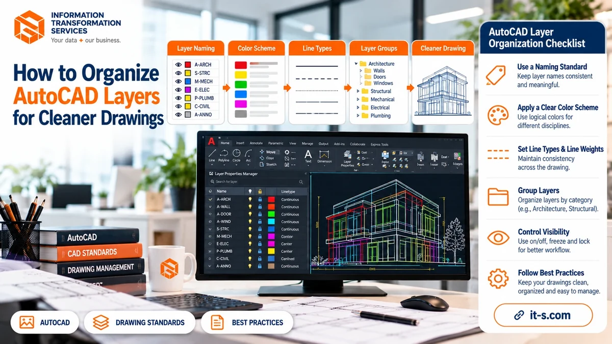
Layer names should describe function rather than personal preference. Names such as Layer1, NewLayer, Final, Lines2, or Misc may make sense to the person who created them, but they become meaningless once the file is shared. A better system uses short, repeatable labels that indicate what the layer contains. Architectural drawings might use names such as A-WALL, A-DOOR, A-DIMS, and A-TEXT, while mechanical drawings might use M-CENTER, M-HIDDEN, M-DIMS, and M-PARTS.
The exact naming convention matters less than consistency. Decide whether separators will use hyphens, underscores, or another pattern, and keep abbreviations stable. If a project includes several disciplines, a prefix can separate architectural, mechanical, electrical, or structural content. This is especially useful when AutoCAD files are later prepared for a broader 2D and 3D modeling workflow, because clear layer names make imported geometry easier to identify in downstream software.
Keep One Visual Purpose Per Layer
A common source of confusion is using one layer for objects that should behave differently. If walls, dimensions, centerlines, and annotations all share the same layer, changing visibility or plotting properties affects all of them at once. Instead, group objects according to how they need to be controlled. Geometry that must use different linetypes, colors, lineweights, or visibility states generally deserves a separate layer.
At the same time, avoid creating a unique layer for every individual object. A layer should represent a meaningful class of drawing information. All standard dimensions can usually share one dimension layer. All centerlines can share one centerline layer. This balance keeps the layer list short enough to navigate while still giving users control over important drawing elements.
Use ByLayer Properties Instead of Manual Overrides
AutoCAD is easiest to maintain when color, linetype, and lineweight are controlled by the layer rather than assigned individually to objects. When an object uses ByLayer properties, changing the layer definition updates every object on that layer automatically. This keeps the drawing visually consistent and makes later revisions faster.
Manual object-level overrides should be exceptions rather than the default. If several objects on the same layer repeatedly need different properties, that usually indicates that the layer structure needs improvement. A clean file lets the layer system do most of the visual work. This principle is particularly helpful in technical drawings that may later support mechanical 3D modeling, where clearly separated construction, center, hidden, and dimension information reduces cleanup before model creation.
Assign Colors With a Consistent Logic
Layer colors can serve two purposes. They help users identify drawing content on screen, and they can also control plotted lineweights when a color-dependent plot style is used. Random color selection makes the layer manager harder to understand and can produce unexpected printing results. Instead, assign colors based on category or plotting importance.
For example, primary geometry may use one group of colors, annotation another, reference information another, and non-printing construction layers another. If the office uses CTB plot styles, confirm that the selected colors correspond to the intended printed thickness. If STB plotting is used, colors can focus more on screen clarity because plot behavior is controlled separately. Either way, the relationship between layer color and output should be documented rather than guessed.
Separate Construction Geometry From Final Geometry
Temporary lines are useful during drafting, but they should not remain mixed with final objects. Create a dedicated construction layer for guide lines, alignment references, temporary circles, layout aids, and other geometry that should not appear in the final drawing. Set that layer to a distinctive color and, when appropriate, configure it not to plot.
This approach keeps the drawing readable during editing while preventing accidental output of helper geometry. It is also useful when cleaning imported CAD files because unwanted construction objects can be isolated and removed quickly. The article on importing CAD files into 3ds Max without losing geometry shows why cleanup before export matters when CAD drawings are reused in visualization workflows.
Give Dimensions and Text Their Own Layers
Dimensions and text often need to be visible in some layouts but hidden in others. Keeping them on dedicated layers gives you that control without affecting the underlying model geometry. Separate layers can also be useful for general notes, room labels, leaders, dimensions, and title information when each category needs different display or plotting behavior.
This separation becomes especially valuable in drawings used at several scales. A dimension set that works on a detailed sheet may clutter a broader plan. With a disciplined layer structure, users can control which annotations appear in a viewport while leaving the model unchanged. The same principle applies to reference marks, centerlines, hidden lines, and section indicators.
Use Layer States for Repeated Views
Large drawings often require different combinations of visible layers for editing, printing, coordination, and presentation. Instead of repeatedly turning layers on and off, save Layer States for common configurations. A working state might show construction geometry and references, while a plotting state hides them. Another state might isolate annotation for checking.
Layer States reduce mistakes because the same visibility configuration can be restored in seconds. They are particularly useful when several people work on the same file or when one model supports multiple sheets. A saved state is more reliable than relying on memory, especially after many layers have been frozen, locked, or switched off during editing.
Lock Layers That Should Not Be Edited
Locking is different from hiding. A locked layer remains visible, but its objects cannot be modified accidentally. This is useful for survey references, existing conditions, background plans, imported consultant drawings, title blocks, or other information that users need to see while drafting but should not change.
Use locking strategically rather than locking everything. Too many locked layers can slow down routine work if users constantly unlock and relock them. The best candidates are reference layers and completed geometry that should remain stable while another part of the drawing is being developed.
Clean Up Duplicate and Unused Layers
Files that have passed through several teams often contain duplicate layers with slightly different names, such as WALL, Walls, A-Wall, WALLS-NEW, and Wall-Final. Before adding more layers, review what already exists. Where two layers serve the same purpose, move the objects to the preferred layer and remove the duplicate when it is safe to do so.
Unused layers should also be purged periodically, especially after importing blocks or external files. Some nested objects bring in layers that remain even after the visible geometry is deleted. Cleaning them reduces clutter in the Layer Properties Manager and makes it easier to find the layers that actually matter. The same kind of disciplined cleanup is helpful before converting drawings into models, as described in the guide on converting CAD drawings into 3D models for visualization.
Be Careful When Moving Objects Between Layers
Changing an object to a new layer does not always remove its old visual settings. If the object was manually assigned a color, linetype, or lineweight instead of using ByLayer, it may continue to look different after the move. After reorganizing a file, inspect the selected objects and return their properties to ByLayer where appropriate.
This is also a good time to check blocks. Objects inside a block can inherit layer behavior differently depending on whether they were created on Layer 0 or on named layers. Blocks intended to change appearance according to the layer on which they are inserted are usually easier to manage when their internal geometry is built with the correct Layer 0 and ByLayer logic.
Use Filters When the Layer List Becomes Large
Even a well-organized commercial drawing can contain many layers. Layer filters make those lists easier to manage by displaying only layers that meet certain conditions. A property filter can show layers with a specific prefix, color, state, or other property, while group filters can collect manually selected layers into practical working sets.
For example, a user may create filters for annotation, architecture, mechanical information, external references, or non-plotting layers. Filters do not change the drawing itself. They simply reduce visual clutter in the Layer Properties Manager, which makes everyday work faster without adding more layers.
Audit the File Before Delivery
Before a drawing is issued, check whether objects are on the intended layers, whether any temporary layers are still visible, and whether plotting behavior matches the project standard. Review frozen, off, locked, and non-plotting layers so nothing important disappears unexpectedly. It is also useful to inspect the drawing for objects left on Layer 0 when they should belong to a project layer.
If the drawing contains fragmented geometry, layer cleanup can be combined with geometric cleanup. For example, the guide on converting multiple lines to a polyline in AutoCAD can help simplify connected linework before final organization. Cleaner geometry and cleaner layers reinforce each other because both reduce the number of small exceptions a drafter must remember.
Conclusion
Organizing AutoCAD layers is less about creating strict complexity and more about making every drawing decision predictable. Clear names, purposeful grouping, ByLayer properties, consistent colors, separate annotation layers, controlled construction geometry, and regular cleanup make a file easier to edit and easier to hand off to someone else.
The best layer system is one that another user can understand without explanation. When objects are placed where expected and visibility can be controlled without hunting through dozens of vague layer names, drawings stay cleaner through revision, coordination, plotting, and later reuse. A few minutes spent designing the layer structure early can prevent hours of cleanup once the project becomes larger.