

How to Optimize CAD Models for 3D Printing Without Losing Accuracy
A CAD model that looks perfect on screen is not automatically ready for 3D printing. Engineering models are often created for design review, machining, simulation, assembly, or documentation, while a 3D printer needs a closed, printable volume that can survive both slicing and the physical limits of the chosen process. Tiny gaps, zero-thickness surfaces, overly fine details, dense meshes, awkward overhangs, and incorrect tolerances can all turn an accurate model into a failed print.
The challenge is to prepare the model for manufacturing without changing the dimensions and features that matter. Good optimization is not the same as making a model simpler at any cost. It means removing unnecessary complexity while preserving functional geometry, fit, scale, and design intent. The most reliable workflow starts in the CAD file, continues through mesh export, and ends with a slicer check before anything is sent to the printer.
Begin With the Manufacturing Purpose of the Part
Before changing geometry, decide what the printed part is expected to do. A visual prototype, a fit-check model, a functional bracket, a casting pattern, and a presentation model have very different accuracy requirements. A decorative housing may tolerate simplified internal features, while a bearing seat or mating flange may depend on precise diameters and hole positions. This distinction matters because optimization should target geometry that does not contribute to the intended use.
It also helps to identify critical dimensions before export. Mark mounting holes, interfaces, snap fits, shafts, slots, sealing surfaces, and any other features that cannot move. If the model was created by another person or imported from another CAD system, compare these dimensions against the drawing or design specification. The broader difference between engineering CAD and general-purpose modeling is discussed in CAD vs 3D modeling, which is useful when deciding where accuracy must be preserved and where visual simplification is acceptable.
Repair the Solid Model Before Exporting a Mesh
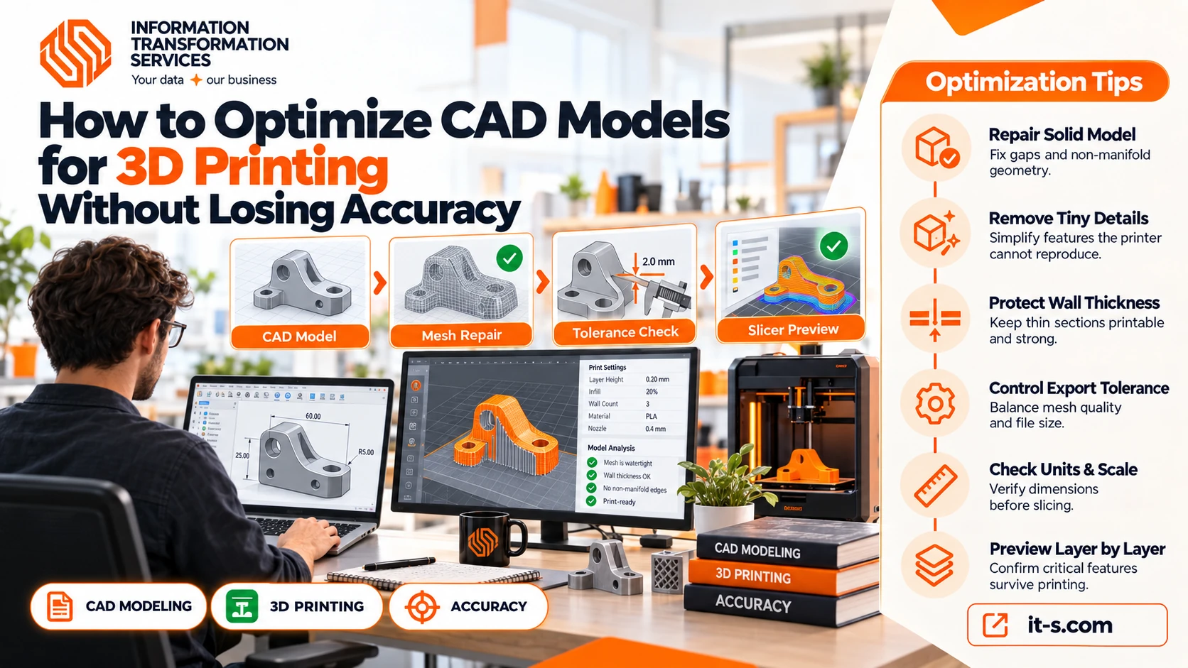
Mesh repair tools can fix many problems, but the best place to correct a defective model is usually the original CAD environment. Confirm that the part is a valid watertight solid rather than a collection of surfaces. Look for open edges, self-intersections, overlapping bodies, duplicate faces, sliver surfaces, and tiny accidental gaps. Boolean operations should resolve cleanly, and joined components that are intended to print as one object should form one coherent volume.
Small CAD defects can become much larger after tessellation. A microscopic gap between surfaces may turn into an open boundary in an STL file, while overlapping solids can create ambiguous internal triangles that confuse a slicer. If a feature is genuinely unnecessary for printing, remove it in CAD rather than relying on automatic mesh cleanup later. This keeps the model history understandable and reduces the chance that repair software will alter a dimension without making the change obvious.
Remove Details the Printer Cannot Reproduce
CAD assemblies often contain more detail than a printer can physically produce. Threads may be modeled with full helical geometry, logos may contain extremely shallow embossing, and imported components can include tiny chamfers, grooves, fillets, screws, seals, or manufacturing marks. These features increase file size and triangle count even when they disappear during slicing.
Compare the smallest feature in the model with the realistic capability of the printing process. A feature narrower than the extrusion width of an FDM printer or smaller than the effective pixel or laser resolution of a resin or powder system may not survive. Removing such details usually does not reduce practical accuracy because the printer could not reproduce them anyway. Keep features that affect function or measurement, but simplify purely visual geometry that falls below the process resolution. This is one reason a carefully prepared model can print more accurately than an untouched high-detail file.
Protect Wall Thickness and Functional Clearances
Thin walls are a common source of failure because CAD software allows geometry that is mathematically valid but physically fragile. Review shells, ribs, fins, tabs, clips, and narrow transitions to ensure they are thick enough for the selected material and process. A wall that slices into one unstable line may print inconsistently even when the nominal dimension in CAD is correct.
Clearance deserves the same attention. Two parts designed with zero clearance will rarely fit after printing because real processes introduce dimensional variation, surface roughness, thermal shrinkage, and support marks. The required allowance depends on the printer, material, orientation, and post-processing, so it should be validated with test pieces rather than treated as one universal number. For mechanical parts, the mechanical 3D modeling section provides useful context on why manufacturing geometry must be designed around real assemblies and interfaces rather than screen appearance alone.
Choose Export Tolerances Instead of Maximum Resolution
When a CAD solid is exported to STL or another mesh format, curved surfaces are approximated by polygons. If the tessellation is too coarse, circles become visibly faceted and curved surfaces lose dimensional fidelity. If it is unnecessarily fine, the file becomes very large without improving what the printer can actually make.
Use chord-height, deviation, and angular controls that match the required accuracy of the part. The mesh should represent the CAD surface more accurately than the printer’s own dimensional capability, but there is little value in generating millions of triangles for a desktop process that cannot reproduce that level of detail. Inspect critical cylinders, arcs, holes, fillets, and mating curves after export. A useful rule is to refine the mesh until another increase in resolution no longer changes the printed geometry in a meaningful way.
Keep Units and Scale Under Control
Some mesh formats do not reliably store unit information, which creates an easy path to major scale errors. A model designed in millimeters can be interpreted as inches or vice versa, producing a part that is dramatically too large or too small. Confirm the document units before export and verify the bounding dimensions after import into the slicer.
This check should not rely only on visual appearance. Read the actual X, Y, and Z dimensions in the slicer and compare them with known CAD measurements. Avoid compensating for a unit mistake by manually scaling the mesh unless there is no better option, because later users may not know that a correction factor was applied. A clean workflow preserves one consistent scale from CAD through slicing. The step-by-step guide on making 3D printer models and files provides additional background on moving from a model to a slicer-ready file.
Optimize Orientation Before Redesigning Geometry
A feature that looks difficult to print in one orientation may be straightforward in another. Before adding supports, thickening every detail, or redesigning the part, evaluate how orientation affects overhangs, layer direction, support contact, dimensional accuracy, and surface finish. Holes printed vertically may behave differently from horizontal holes, and a long thin component may be stronger in one direction but more dimensionally stable in another.
Orientation can also protect critical surfaces. A precision face placed against heavy support structures may require post-processing that changes its dimensions. Moving that surface upward or rotating the part can sometimes preserve it without modifying the CAD model. Treat orientation as part of design optimization rather than a last-minute slicer setting. For complicated parts, test several orientations and compare estimated support volume, layer count, contact areas, and the direction of expected loads.
Use Mesh Reduction Carefully
Decimation and polygon reduction can be valuable when an exported file is unnecessarily heavy, but they should be applied selectively. Flat surfaces can often lose many triangles with no geometric change, while small-radius curves and precise cylindrical features are much more sensitive. Automatic reduction algorithms may preserve the overall appearance while subtly changing hole diameters, edge locations, or curvature.
Always keep the original CAD model and an unreduced export. If reduction is needed, compare the optimized mesh against the reference using deviation analysis when possible. Pay particular attention to mating surfaces and measurement-critical geometry. Polygon count is not itself a quality metric. A well-structured moderate-resolution mesh can describe a mechanical part more faithfully than a huge file filled with redundant triangles. The objective is efficient geometry, not the smallest possible file.
Check the Model in the Slicer Layer by Layer
A model should not be considered ready simply because the slicer accepts it. Preview the generated layers and inspect how important features are actually being translated into toolpaths or exposure areas. Look for missing walls, filled holes, disconnected islands, thin sections that disappear, unexpected internal material, and sudden changes in contour. These problems reveal whether geometry that exists in CAD survives the final manufacturing interpretation.
The layer preview is also where excessive detail becomes obvious. If a complex groove or surface feature never appears in the toolpath, it is adding CAD and mesh complexity without contributing to the print. Conversely, if a functional edge appears only intermittently across layers, it may need a design adjustment. This last check connects the digital model to the actual fabrication process and often catches errors that are invisible in a shaded 3D viewport.
Validate Accuracy With a Small Test Print
For parts with demanding fits or tolerances, a small test is usually more informative than further theoretical optimization. Print the critical interface, hole pattern, snap fit, thread section, or representative wall instead of the entire component. Measure the result with appropriate tools and compare it with the CAD dimensions. This reveals systematic offsets caused by the printer, material, settings, and orientation.
Apply corrections to the design only when the measurements show a repeatable need. Avoid changing every nominal dimension after one imperfect print, because isolated errors may come from calibration, warping, support removal, or inconsistent process conditions. A controlled test-and-measure approach preserves the original engineering intent while adapting the file to the realities of the chosen manufacturing method.
Conclusion
Optimizing a CAD model for 3D printing is a balance between geometric fidelity and manufacturability. The most reliable process begins by identifying functional dimensions, repairing the solid model, removing details that cannot be printed, checking wall thickness and clearances, and exporting a mesh at an appropriate tolerance. Scale, orientation, polygon reduction, and slicer inspection then refine the file without sacrificing the geometry that matters.
Accuracy is best protected when every simplification has a reason. Reducing file size is useful only if the part remains dimensionally faithful, and adding detail is useful only if the printer can reproduce it. By keeping the original CAD model as the reference and validating critical features through slicer previews and test prints, designers can create files that are lighter, more reliable, and more likely to produce the intended physical result on the first successful run.