


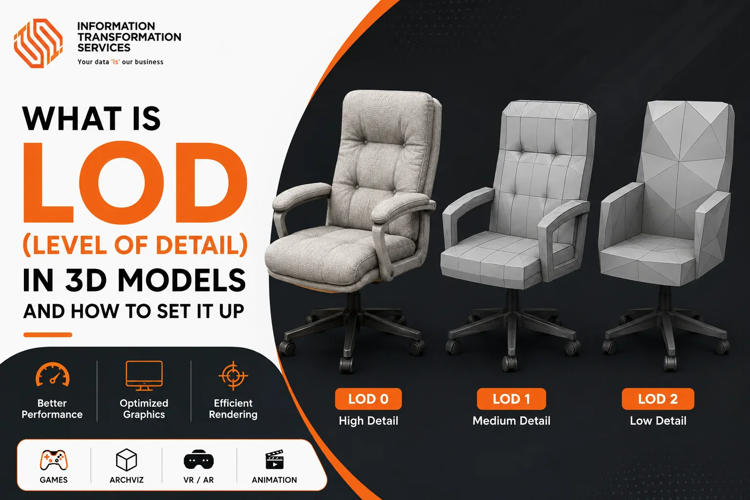
What Is LOD (Level of Detail) in 3D Models and How to Set It Up?
LOD (Level of Detail) in 3D models is a real-time optimization method that replaces a detailed mesh with simpler versions as the object occupies less screen space. To set it up, preserve the game-ready asset as LOD0, create progressively reduced LOD1–LOD3 meshes, and assign screen-size transitions in the game engine. The process requires more than lowering triangle count: silhouette, normals, UVs, material slots, pivots, and draw calls must remain controlled. This guide shows how to build each level, prevent visible popping, and verify that the finished setup reduces rendering workload on target hardware.
How Does LOD Work in a 3D Model?
LOD works by tracking how much screen space a 3D model occupies and selecting the least complex version that still preserves its visible shape. When the object is close, the game engine displays LOD0 with full geometry. As it becomes smaller, LOD1, LOD2, and LOD3 progressively replace it with meshes containing fewer triangles, simpler materials, or fewer renderers. This is the core principle behind LOAD optimization in real-time rendering.
The transition should occur only after the details removed from the next level are difficult to see. If a lower mesh changes the silhouette, shading, or material appearance too early, the switch becomes noticeable as LOD popping. The final level may use a very simple mesh, impostor, or billboard before the object reaches its culling range.
Screen size gives more dependable control than a fixed camera distance. The same distance produces different visual results for a small prop, a large building, or a camera using a different field of view. Transition points should therefore be tested with the actual gameplay camera and adjusted according to the asset’s visible size. Unity similarly describes LOD as a way to reduce polygons, materials, or renderers as an object becomes smaller on screen .
How Many LOD Levels Should You Create?
For many real-time assets, two to four LOD levels provide a practical starting point, although the correct number depends on asset complexity, screen coverage, repetition, and maximum viewing distance. A small prop may require only LOD0 and LOD1, while a frequently repeated environment asset, building, vehicle, or character can benefit from LOD0 through LOD3. Extremely distant objects may finish with an impostor or billboard instead of another mesh.
Use the fewest levels that cover the asset’s visible range without leaving unnecessary geometry on screen. Add another stage when the current mesh remains too detailed at long distance or when the difference between two existing levels creates a noticeable jump. Skip additional versions when the object stays close to the camera, already has a low rendering cost, or appears too briefly to justify the work. Extra meshes increase production time and memory, so their value should be confirmed in a representative scene rather than assumed.
How to Set Up LOD Levels for a 3D Model
To set up LOD levels, begin with a validated game-ready mesh, create simplified versions in controlled stages, optimize their materials, and import them with consistent names and transforms. Configure each transition by screen size, correct any visible popping, and measure the finished result in a representative scene. The following workflow keeps geometry reduction, visual quality, and performance testing connected throughout the process.
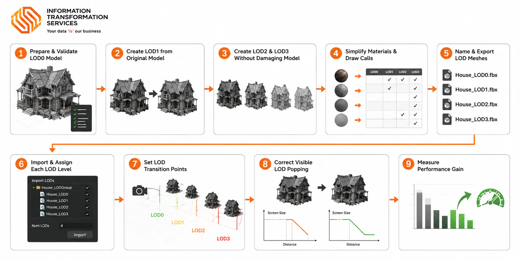
Step 1: Prepare and Validate the LOD0 Model
Start by selecting the final game-ready mesh as LOD0, the highest-detail version displayed close to the camera. Avoid using a raw sculpt or unfinished source model because every lower LOD level will be created and evaluated against this mesh.
Duplicate the approved model, name it AssetName_LOD0, and preserve the original as a backup. Apply or freeze its transforms, confirm the intended scale and orientation, and place the pivot where the object should rotate or rest inside the game engine.
Inspect the geometry for duplicate vertices, overlapping faces, incorrect normals, and internal surfaces that are not required for shadows, reflections, animation, destruction, or any expected camera angle. Check the UVs for distortion and remove unused material slots that could create avoidable submeshes and draw calls.
Export LOD0 and test it in the target engine before simplifying it. Confirm that its size, position, materials, shading, and animation appear correctly. Performing this test import early prevents a pivot or scale error from being copied into every lower mesh and causing visible movement during transitions.
Record the engine-reported triangle and vertex counts, material slots, and asset memory. Save representative-scene performance measurements for Step 9, where GPU and CPU frame time can be compared under controlled conditions.
Step 2: Create LOD1 from the Original Model
Create LOD1 as the first simplified version of LOD0, designed for the point where the model begins to occupy less screen space. It should reduce the rendering workload without producing an obvious change during the LOD transition.
Duplicate AssetName_LOD0, rename it AssetName_LOD1, and simplify it through manual retopology, decimation, or automatic LOD generation. Retaining approximately 50–75% of the original triangles provides a useful testing range, not a universal requirement.
Remove hidden geometry, small bevels, shallow surface details, and edge loops that no longer affect the model at medium distance. Preserve the outer silhouette, hard edges, openings, thin components, UV seams, and recognizable features.
Reduce the mesh through several controlled passes rather than one aggressive operation. In Blender, keep the Decimate modifier non-destructive until the silhouette, UVs, normals, and shading have been inspected from typical gameplay angles at the intended screen size.
LOD1 is ready when its triangle count is meaningfully lower, its pivot and materials still align with LOD0, and switching between both meshes produces no visible shift, missing component, or distracting silhouette change.
Step 3: Create LOD2 and LOD3 Without Damaging the Model
Build LOD2 and LOD3 after LOD1 has passed its visual check. These levels should remove geometry that no longer affects the object once it occupies only a small area of the screen.
Return to the clean LOD0 source or use a non-destructive modifier setup. Test approximately 20–35% of the original triangles for LOD2 and 5–15% for LOD3. Repeatedly decimating an already simplified mesh often produces stretched triangles and uneven shading, so evaluate each target from a clean source whenever the tool allows it.
Strip away internal faces, minor bevels, shallow grooves, small attachments, and closely spaced edge loops. Bake surface details into normal maps only when the UV and texture workflow supports the additional bake without creating unnecessary memory cost.
Protect rooflines, wheels, openings, branches, and other features that define the asset from a distance. Removing a small but recognizable part can create a stronger visual jump than reducing thousands of surface triangles.
Preview each mesh at its intended screen size, then compare LOD1 with LOD2 and LOD2 with LOD3. Restore only the geometry responsible for visible shrinking, flickering, or silhouette changes. The lower levels should remain recognizable during camera movement and change progressively rather than abruptly.
Step 4: Simplify Materials and Draw Calls for Distant LODs
Simplify the materials used by distant meshes because lowering the triangle count alone may not reduce rendering cost. A model with several submeshes and complex shaders can remain expensive even after aggressive polygon reduction.
Open the material list for each version and remove unused slots. Merge compatible surfaces where possible, since every retained submesh can require a separate draw call.
Bake small surface details into normal maps and combine suitable textures into an atlas when the memory trade-off is justified. For LOD2 and LOD3, remove shader features that are no longer visible, such as parallax, clear coat, detailed secondary normals, or expensive reflections. Preserve opacity when it defines the silhouette of foliage, fences, hair, or other thin assets, while checking the remaining alpha overdraw.
Avoid creating a separate low-resolution texture set automatically. Additional textures consume memory, so reusing the existing maps with a simpler material can be more efficient when memory is the main constraint.
Force the engine to display each distant level and inspect it with a frame debugger or profiler. Compare material passes, draw calls, texture memory, and GPU frame time rather than judging 3D model optimization through triangle count alone. The revised materials should preserve the asset’s appearance at their intended range while producing a measurable reduction in rendering work.
Step 5: Name and Export the LOD Meshes
Give every mesh the same base name followed by its level, such as Vehicle_LOD0, Vehicle_LOD1, Vehicle_LOD2, and Vehicle_LOD3. Consistent suffixes help the import pipeline recognize that the files belong to one LOD group. Unity supports the _LODX convention when importing externally authored levels.
Align all versions at the same origin before export. Match their pivot, scale, rotation, and forward direction exactly; otherwise, the object may shift, resize, or rotate when the game engine changes levels.
Apply or freeze transforms and use consistent units, coordinate settings, and triangulation rules. Preserve the UV channels and material mappings required by each version, or deliberately update them when distant levels use an atlas or simplified material.
For animated assets, bind every level to a compatible skeleton. Preserve the required bone mapping and inspect skin weights around joints before sending the meshes to the engine.
Export all levels in one FBX when the target pipeline supports automatic detection. If separate files are required, keep their export preset and base name consistent. Perform a test import and switch between the meshes while the camera remains still; correct any movement, missing material, shading change, or animation error at the source.
Step 6: Import and Assign Each LOD Level
Import the prepared files into the game engine and place every mesh in its matching level. Assign the original model to LOD0, followed by the simplified versions in descending order of detail.
In Unity, add an LOD Group component to the asset’s root object and connect the correct Mesh Renderer or Skinned Mesh Renderer to each level. For multi-part models, include every required renderer; an unassigned component will disappear when the transition occurs.
In Unreal Engine, open the asset in the Static Mesh Editor and import or generate each version under the correct LOD index. Check the displayed triangle counts to confirm that geometry decreases from one level to the next. Force the editor to preview each version separately before enabling automatic switching. Examine materials, normals, shadows, scale, animation, and detachable parts. This controlled preview exposes missing renderers and incorrect assignments more reliably than moving the camera immediately.
Review the model bounds and final culling range as well. Bounds that are too small can remove the asset while it is still visible, making the issue look like a failed transition. Every level should appear in the correct slot and retain all required components before transition tuning begins.
Step 7: Set the LOD Transition Points
Configure each transition according to the model’s screen coverage rather than relying on a fixed camera distance. Unity uses screen-relative transition height, while Unreal Engine expresses the change through screen size.
Test with the actual gameplay camera and its intended field of view. A threshold selected in the asset preview may behave differently when the model appears inside the real scene.
Force LOD0 to remain visible and move the camera backward until the details removed from LOD1 can no longer be distinguished. Use the screen-size value at that position as the initial transition point.
Repeat the process between LOD1 and LOD2, then between LOD2 and LOD3. Compare adjacent meshes instead of measuring every version against the original, as a large jump can occur between two lower levels.
Run the camera toward and away from the asset at normal gameplay speed. If a roofline, wheel, branch, or character feature changes noticeably, push the threshold farther away or restore the geometry controlling that feature. Check platform-specific LOD bias and quality settings before reusing the same values on mobile, PC, console, or VR. Keep the thresholds only when progressively cheaper meshes appear without attracting attention during ordinary movement.
Step 8: Correct Visible LOD Popping
Fix LOD popping by identifying what changes at the transition instead of hiding every issue with a longer fade. The usual causes are a shifting silhouette, inconsistent shading, different materials, or mismatched transforms.
Pause the camera near the affected threshold and alternate manually between the two neighboring levels. Keeping the viewpoint fixed makes even a small change in shape, position, lighting, or texture easy to isolate.
Restore only the vertices responsible for a visible silhouette jump. When two versions differ too greatly, introduce an intermediate level rather than moving an unsuitable low-detail mesh closer to the camera.
Treat a lighting flash separately from a geometry change. Compare normals, tangents, hard edges, UV seams, texture assignments, and material parameters. Correct the shared pivot, scale, and rotation if the entire asset moves during the switch.
Enable cross-fading or dithering after the meshes already match closely. These techniques briefly blend information from both versions, so excessive fade ranges can add rendering work and produce ghosting on transparent materials. Test the correction while approaching and leaving the object at gameplay speed; the lower-detail mesh should remain visually unobtrusive and still appear early enough to provide its intended saving.
Step 9: Measure the Performance Gain
Validate the LOD setup with a controlled performance test rather than assuming that fewer triangles automatically produce a faster scene. The comparison must use identical camera movement, lighting, resolution, and quality settings.
Build a representative scene containing the number of assets expected during gameplay. Record a baseline with every object forced to LOD0, then repeat the same camera path with automatic switching enabled.
Allow shaders and textures to finish loading before capturing data. Track visible triangles, draw calls, GPU frame time, CPU render-thread time, and memory use through the engine profiler. Compare frame time in milliseconds because FPS can be distorted by VSync or short fluctuations.
Run several passes in a standalone build on the target PC, console, mobile device, or VR headset. Editor overhead can hide a small gain or create a result that will not appear in the shipped project.
If triangle count falls but GPU time barely changes, inspect material complexity, transparency, overdraw, shadows, lighting, and draw calls. Excessive memory growth may indicate unnecessary mesh levels or duplicated texture sets. Keep the configuration only when repeated captures show lower rendering cost and the camera path remains free from distracting transitions, shading flashes, or disappearing components.
Conclusion
LOD in 3D models is effective only when simpler meshes appear after their removed details have become difficult to see. A reliable setup begins with a clean LOD0, continues through controlled mesh simplification and material reduction, and uses screen-size thresholds that suit the actual gameplay camera. Consistent pivots, normals, UVs, material assignments, and export settings prevent distracting shifts or shading changes between levels.
Cross-fading can smooth a well-prepared transition, but it cannot repair an unsuitable mesh. Whether the asset is configured in Blender, Unity, Unreal Engine, or another real-time pipeline, the final decision should come from target-hardware profiling. The best LOD setup is not the one with the lowest triangle count; it is the one that preserves visual stability while producing a repeatable reduction in rendering cost.