


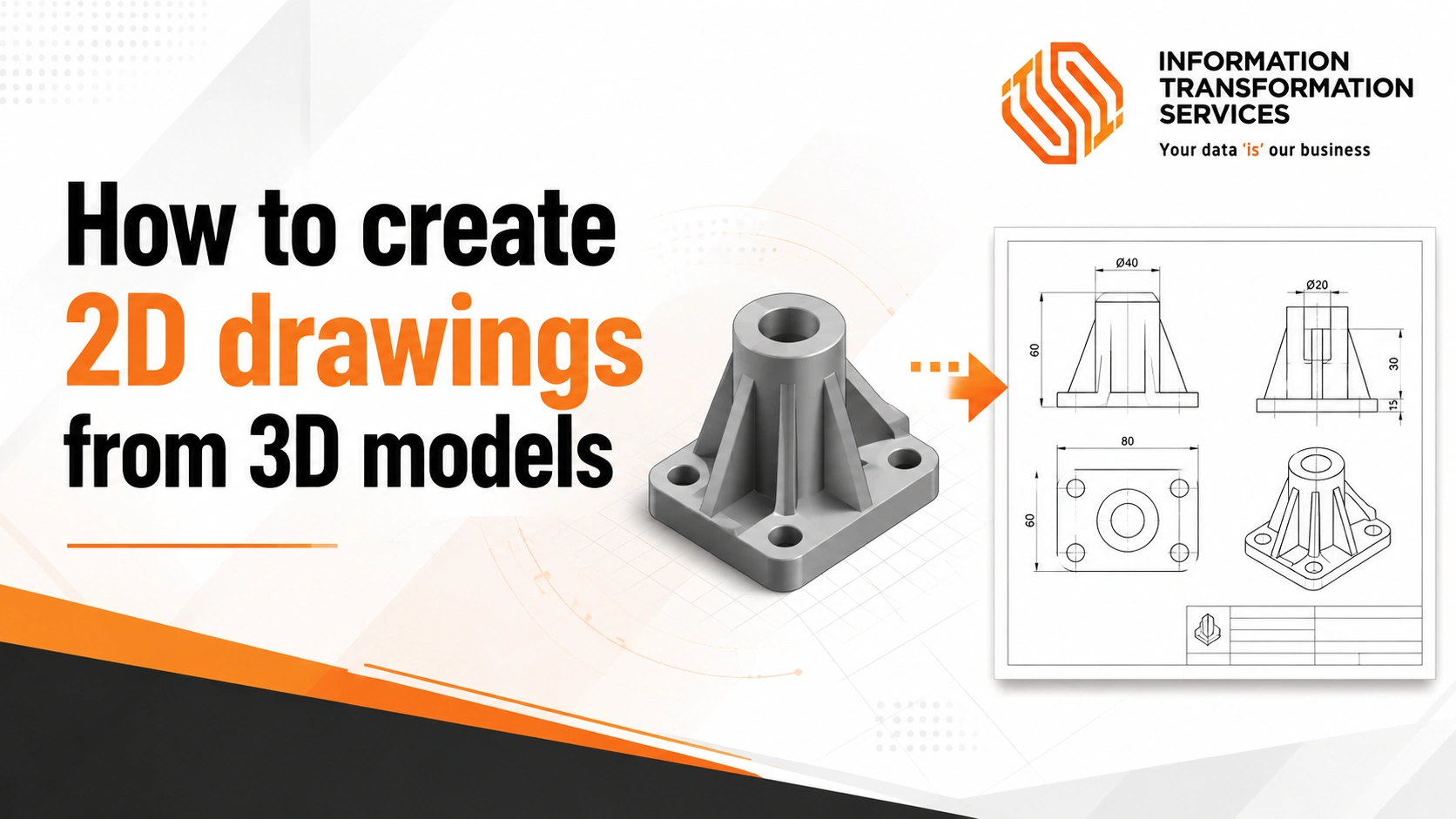
How to create 2D drawings from 3D models
Creating accurate 2D drawings from a 3D CAD model is an essential part of engineering, manufacturing, and product design. Whether you’re designing a single part or a complex assembly, detailed drawings help manufacturers, machinists, and quality inspectors understand exactly how to produce the final product.
If you’re wondering how to create 2D drawings from 3D models, the process is straightforward when you follow the right workflow. Most modern CAD software lets you generate associative 2D drawings by creating a drawing sheet, placing standard views, adding dimensions and manufacturing annotations, reviewing the drawing, and exporting it in the required file format.
In this guide, you’ll learn the complete step-by-step process, the essential drawing elements to include, common mistakes to avoid, and best practices for creating clear, professional, and manufacturing-ready 2D drawings
Before You Start: What You’ll Need
Before you create a 2D drawing, take a few minutes to prepare your files and settings. A complete 3D model and the right drawing setup will save time, reduce errors, and help you create a clear, manufacturing-ready drawing on your first attempt.
Here’s what you should have before you begin:
- A 3D CAD model of the part or assembly you want to document.
- CAD software that can generate 2D drawings, such as SolidWorks, Fusion 360, Autodesk Inventor, Creo, CATIA, Siemens NX, or FreeCAD.
- A drawing template with the correct sheet size, title block, and projection standard.
- The required drawing standard (ISO, ANSI, or ASME) based on your project or customer specifications.
- Design details such as material, dimensions, tolerances, and any notes that need to appear on the final drawing.
With these essentials ready, you’re set to follow the step-by-step process and create an accurate, professional 2D drawing from your 3D model.
Choose the Right Drawing Standard
Before creating a 2D drawing, choose the drawing standard that matches your project requirements. Drawing standards define how dimensions, tolerances, symbols, and annotations appear, ensuring everyone interprets the drawing correctly.
- ISO (International Organization for Standardization): Commonly used for international engineering and manufacturing projects.
- ANSI (American National Standards Institute): Primarily used for engineering drawings in the United States.
- ASME Y14.5 (American Society of Mechanical Engineers): Defines Geometric Dimensioning and Tolerancing (GD&T) for precise manufacturing and inspection.
Step-by-Step Process to Create 2D Drawings from 3D Models
Modern CAD software makes it easy to turn a 3D model into a detailed 2D drawing. While the buttons and menus may differ between programs, the overall workflow remains almost the same. By following the steps below, you can create accurate, manufacturing-ready drawings that are easy to read and update.
Step 1: Open and Review Your 3D Model
Open the 3D CAD model you want to convert into a 2D drawing. Before creating the drawing, spend a few minutes reviewing the model to make sure it is ready for documentation.
Rotate the model and inspect it from different angles. This helps you spot missing features or design issues that may not be visible from a single view.
Next, check that all important features are present. For example, confirm that holes, fillets, chamfers, slots, threads, and cutouts appear exactly where they should. If you’re working with an assembly, make sure every component is in the correct position.
Now compare the model with your design requirements. Verify that the overall size, key dimensions, and feature locations match the final design. If you made recent changes, save the latest version before moving to the next step.
Taking a few minutes to review the model now can prevent missing dimensions, incorrect drawing views, and extra revisions later in the process.
What to check before moving on:
✓ The model opens without errors.
✓ All required features are complete.
✓ Parts are assembled correctly (if applicable).
✓ The latest design changes are saved.
✓ The model is ready to create drawing views
Step 2: Create a New Drawing File
Once your 3D CAD model is ready, create a new 2D drawing in your CAD software. Most CAD programs include a drawing workspace that automatically links the drawing to your 3D model. This means any future changes to the model can update the drawing without starting over.
When the new drawing opens, choose a drawing template that matches your project. The template controls the sheet layout, title block, units, and projection standard, so selecting the correct one saves time later.
Next, select the sheet size based on the size and complexity of your part or assembly. Use a larger sheet if your design needs multiple views or detailed dimensions. Then choose an appropriate drawing scale so every feature is clear and easy to read without making the drawing look crowded.
Before moving to the next step, confirm that the sheet is set up correctly. A well-prepared drawing file makes it easier to place views, add dimensions, and create a clean, professional engineering drawing.
Before you continue, make sure:
✓ The new drawing file is linked to your 3D model.
✓ The correct drawing template is selected.
✓ The sheet size fits your design.
✓ The drawing scale makes the model easy to read.
✓ The units and projection standards match your project requirements.
Step 3: Insert Standard Drawing Views
Now it’s time to place the views that show your model from different angles. These drawing views help manufacturers understand the shape, size, and features of the part without viewing the 3D model.
Start by placing the front view. This is usually the main view because it shows the part most clearly. Then add the top and right-side views. These standard orthographic views provide a complete picture of the design and reduce the chance of misinterpretation.
Next, add an isometric view if you want to show the part in a realistic 3D-like perspective. Although manufacturers usually don’t use it for measurements, it helps anyone reading the drawing quickly understand the overall shape.
If some internal or small features are difficult to see, add a section view or detail view. A section view reveals hidden internal features, while a detail view enlarges a small area so dimensions and notes remain easy to read.
As you place each view, leave enough space between them. This gives you room to add dimensions, annotations, and manufacturing notes later without making the drawing look crowded.
Your drawing file is ready if:
✓ The front view clearly represents the part.
✓ Top and side views align correctly with the front view.
✓ The isometric view improves visual understanding.
✓ Section or detail views are added only where needed.
✓ There is enough space for dimensions and annotations.
Step 4: Add Dimensions
Dimensions define the exact size and position of every feature on the part. Without them, manufacturers cannot produce the part accurately, even if the drawing views are clear.
Begin by adding the overall dimensions for the part, including its length, width, and height. Then dimension important features such as holes, slots, cutouts, fillets, and chamfers. Use the measurements from your 3D CAD model to keep the 2D drawing accurate and consistent.
Place each dimension where it is easy to read. Leave enough space between dimension lines and avoid crossing them whenever possible. A clean layout improves readability and helps machinists and inspectors find measurements quickly.
Include only the dimensions required to manufacture and inspect the part. Avoid repeating the same measurement in different locations, as duplicate dimensions can cause confusion and lead to production errors.
Check Your Dimensions
✓ All critical features are fully dimensioned.
✓ No dimensions are duplicated.
✓ Dimension lines are clear and easy to read.
✓ Every measurement matches the 3D model.
✓ The drawing includes all information needed for manufacturing and inspection.
Step 5: Add Manufacturing Annotations
Dimensions tell manufacturers how big a feature is, but manufacturing annotations explain how it should be made, finished, or inspected. Adding these details makes your 2D engineering drawing complete and reduces the need for clarification during production.
Start by adding notes that provide important instructions. For example, you can specify the material, surface treatment, coating, or any special manufacturing requirements.
Next, insert center marks and centerlines for holes and circular features. These symbols make the drawing easier to read and help machinists locate features accurately.
If your part contains threaded or drilled holes, include hole callouts. They provide essential information such as hole size, depth, thread type, and quantity without overcrowding the drawing.
Complete the drawing by reviewing the title block. Make sure it includes the drawing title, part number, revision, scale, units, and any other project details required by your company or customer.
Keep all annotations close to the related feature while avoiding overlaps with dimensions or drawing views. A clean layout helps everyone understand the drawing quickly and minimizes production errors.
Review Your Annotations
✓ Manufacturing notes are clear and easy to understand.
✓ Center marks and centerlines are added where needed.
✓ Hole callouts include complete information.
✓ The title block contains the correct project details.
✓ Notes and symbols do not overlap with dimensions or drawing views.
Apply Tolerances and GD&T
Not every part needs to match its exact dimension perfectly. Tolerances define the acceptable variation, while Geometric Dimensioning and Tolerancing (GD&T) controls the shape, position, and orientation of critical features. These details help manufacturers produce parts that fit and function as intended.
Start by identifying the features that require tighter control, such as holes, mating surfaces, or precision-machined areas. Apply dimensional tolerances based on the part’s function and manufacturing process. Avoid using extremely tight tolerances unless they are necessary, as they can increase production time and cost.
If your project follows GD&T standards, add the appropriate symbols to control important features. For example, you may specify the position of a hole, the flatness of a surface, or the perpendicularity between two features. Use these symbols only where they add value and match your design requirements.
Finally, review each tolerance to ensure it supports the part’s intended use. Every tolerance should have a clear purpose and should not conflict with other dimensions or notes on the drawing.
Confirm Your Tolerances
✓ Critical features have the required tolerances.
✓ GD&T symbols are applied correctly where needed.
✓ Tolerances match the part’s function and manufacturing process.
✓ No tolerance conflicts with existing dimensions or notes.
✓ The drawing provides enough information for accurate manufacturing and inspection.
Step 7: Review the Drawing
A final review helps you catch mistakes before the drawing reaches the shop floor. Spending a few extra minutes on this step can prevent manufacturing delays, rework, and costly revisions.
Read through the entire 2D drawing from top to bottom. Check that every drawing view is clear and that all dimensions, annotations, and tolerances are easy to understand. Make sure nothing overlaps or hides important information.
Next, compare the drawing with the 3D CAD model. Confirm that all important features appear in the drawing and that every dimension matches the latest version of the model. If you updated the model during the design process, ensure the drawing reflects those changes.
Finally, review the title block and revision information. Verify that the part number, drawing title, scale, units, and revision level are correct before sharing the drawing with your team or manufacturer.
Final Drawing Review
✓ All drawing views are complete and correctly aligned.
✓ Dimensions, annotations, and tolerances are accurate.
✓ The drawing matches the latest 3D model.
✓ The title block and revision details are correct.
✓ The drawing is clear, complete, and ready for manufacturing.
Step 8: Export the Drawing
After reviewing the drawing, export it in the file format required for manufacturing, sharing, or documentation. Choosing the right format ensures that everyone can open and use the drawing without losing important details.
If you need a file for printing or approval, export the drawing as a PDF. For CNC machining, fabrication, or further CAD editing, DWG and DXF are the most common formats because they preserve the drawing geometry.
Before saving the final file, check the sheet size, drawing scale, and print settings. Open the exported file to confirm that all drawing views, dimensions, annotations, and tolerances appear correctly. A quick review helps you catch formatting issues before sending the drawing to a client, supplier, or manufacturer.
Store the exported file with a clear name and revision number. This makes it easier to identify the latest version and avoids confusion when multiple revisions exist.
Ready to Share Your Drawing?
✓ The correct file format is selected (PDF, DWG, or DXF).
✓ All drawing views display correctly.
✓ Dimensions and annotations are complete and readable.
✓ The file name includes the correct revision, if applicable.
✓ The exported drawing is ready for manufacturing, review, or documentation.
You’ve now completed the full process of creating a 2D drawing from a 3D model.
Which CAD Software Fits Your Needs?
Every CAD program can create 2D drawings from 3D models, but each one offers different strengths.
- SolidWorks simplifies the creation of manufacturing drawings with automatic drawing updates, making it a popular choice for mechanical design.
- Autodesk Inventor provides powerful tools for documenting parts, assemblies, and production-ready engineering drawings.
- Fusion 360 combines CAD, CAM, and cloud collaboration in one platform, making it ideal for small teams, startups, and product designers.
- Creo Parametric includes advanced modeling, simulation, and GD&T tools for complex engineering projects.
- CATIA manages large assemblies and detailed product designs used in industries such as aerospace and automotive.
- Siemens NX supports end-to-end product development with advanced design, simulation, and manufacturing capabilities.
- FreeCAD offers a free, open-source solution for learning CAD and creating basic engineering drawings.
No single software is the best for every project. The right choice depends on your industry, project complexity, budget, and workflow. Regardless of the software you use, the core process of creating accurate 2D engineering drawings remains the same.
Why Are 2D Drawings Still Important?
A 3D CAD model shows what a part looks like, but it doesn’t tell manufacturers everything they need to build it. A 2D engineering drawing adds the dimensions, tolerances, materials, and notes that guide production from start to finish.
Even with modern CAD software, many workshops and manufacturers ask for 2D drawings because they are quick to review, easy to print, and simple to share with different teams.
Here are the main reasons they still matter:
- Guide manufacturing: Machinists use drawings to machine, cut, drill, weld, or assemble parts according to the design.
- Check part accuracy: Quality inspectors compare the finished part with the drawing to confirm that every critical dimension and tolerance meets the required specifications.
- Improve team communication: Engineers, suppliers, and production teams can review the same drawing without opening the original 3D CAD model.
- Track design changes: Revision tables help teams identify the latest version and prevent outdated drawings from reaching production.
- Reduce costly mistakes: Clear dimensions, annotations, and tolerances help teams build the correct part the first time.
A 3D model helps you design a product, while a 2D drawing tells others how to manufacture and inspect it. In most engineering projects, both work together to deliver accurate results.
Common Mistakes to Avoid When Creating 2D Drawings
Even a small error in a 2D drawing can cause confusion during manufacturing. Avoiding common mistakes helps you save time, reduce revisions, and create more accurate engineering drawings.
Missing Important Dimensions
Every feature that needs to be manufactured or inspected should have the required dimensions. Missing measurements force manufacturers to guess, which can lead to incorrect parts.
Adding Too Many Dimensions
More dimensions do not always make a drawing better. Adding the same measurement in multiple places can confuse the reader and create conflicts if one value changes.
Choosing the Wrong Drawing Scale
A drawing that is too small makes dimensions difficult to read, while an oversized drawing wastes space. Select a scale that shows every feature clearly.
Using Unnecessary Drawing Views
Every drawing view should have a purpose. Remove duplicate or unnecessary views to keep the drawing clean and easy to understand.
Forgetting Tolerances
Critical features often require tolerances to control size or position. Without them, manufacturers may produce parts that do not fit or function correctly.
Ignoring the Title Block
The title block contains important information such as the part name, drawing number, revision, scale, and units. Always review this information before releasing the drawing.
Skipping the Final Review
Many drawing errors appear during a final check. Review the drawing one last time to confirm that all views, dimensions, annotations, and tolerances are correct.
Avoid These Errors
✓ Include all required dimensions.
✓ Remove duplicate dimensions.
✓ Select a clear drawing scale.
✓ Add only the views you need.
✓ Apply tolerances to critical features.
✓ Check the title block before sharing the drawing.
✓ Review the finished drawing before exporting it.
By avoiding these common mistakes, you can create 2D engineering drawings that are easier to read, simpler to manufacture, and less likely to require revisions.
Best Practices for Creating Professional 2D Drawings
A few good habits can improve the quality of your 2D drawings and make them easier to manufacture, inspect, and update. Use these best practices every time you create a new drawing.
Select the Best View First
Choose the front view that shows the most important features of the part. Then place the top and side views in alignment. Add section or detail views only when they help explain hidden or complex features.
Keep the Layout Easy to Read
Leave enough space between drawing views, dimensions, and annotations. A clean layout makes it easier to find information and reduces the chance of misreading the drawing.
Follow One Drawing Standard
Use the drawing standard required for your project, such as ISO, ANSI, or ASME. Applying one standard keeps symbols, dimensions, and annotations consistent throughout the drawing.
Dimension Every Critical Feature
Add dimensions only where they are needed for manufacturing and inspection. Avoid duplicate dimensions because they can create confusion if the design changes later.
Review the Drawing After Every Design Change
Whenever you update the 3D CAD model, open the 2D drawing and check that every view, dimension, annotation, and tolerance reflects the latest design. This simple review helps prevent outdated drawings from reaching production.
Keep Revision Information Up to Date
Update the revision number whenever you make a design change. This helps engineers, suppliers, and manufacturers identify the latest drawing and avoid working from an older version.
How ITS Supports Professional 3D Modeling and Engineering Drawings
High-quality 2D engineering drawings begin with an accurate 3D CAD model. At ITS, we create detailed mechanical models that help engineers, manufacturers, and product designers produce clear, production-ready drawings.
Our team has experience working on a wide range of mechanical components, from single machine parts to large assemblies. We also support projects across the automotive, aerospace, electronics, and general manufacturing industries, where precision is critical.
Our expertise includes:
- Creating detailed 3D models for machine parts.
- Building complete assemblies with multiple components.
- Developing multi-view models for engineering documentation.
- Modeling automotive, aerospace, industrial, and electronic components.
- Converting 2D sketches and legacy drawings into accurate 3D CAD models for professional engineering documentation.
Whether you start with a hand sketch, an existing drawing, or a product concept, we focus on building accurate CAD models that make 2D drawing creation faster, easier, and more reliable.
Conclusion
Creating a 2D drawing from a 3D model is a straightforward process when you follow the right workflow. Start with a complete 3D CAD model, create a properly configured drawing file, place the required views, and add clear dimensions, annotations, and tolerances. Finish by reviewing the drawing carefully and exporting it in the correct file format.
Whether you’re creating a simple part drawing or a detailed assembly drawing, clear documentation helps manufacturers, inspectors, and production teams understand your design with confidence. By applying the steps and best practices in this guide, you can create accurate, professional 2D engineering drawings for a wide range of engineering and manufacturing projects.