What Are Some Common SolidWorks Workflows For Product Design?
Designers from various industries extensively utilize SolidWorks, a well-liked Computer-Aided Design (CAD) software solution, while creating products. It provides a complete collection of tools and workflows, including 2D sketches, 3D models, assembly models, simulations, renderings, and technical documentation enabling designers to create products from the initial concept stage to the final production-ready model. This blog article will look at a few common SolidWorks product design workflows.
An Overview of SolidWorks:
SolidWorks is a 3D computer-aided design (CAD) software widely used by engineers and designers to create, simulate, and manufacture products. It was developed by Dassault Systèmes, a French company specializing in software solutions for product design, simulation, and manufacturing. Basically, SolidWorks is a parametric CAD software, which means that it allows users to create models using parametric relationships. Parametric relationships are constraints used to define a model’s geometry and behavior. For example, users can sketch a part and add dimensions and constraints to define its size and shape. They can then modify the dimensions or constraints, and the model will update automatically to reflect the changes. This parametric capability makes SolidWorks a powerful tool for designing complex geometries. SolidWorks also includes a range of tools for simulation and analysis. These tools enable designers to test the performance of their product under different conditions, such as temperature, pressure, and vibration. The simulation results can be used to optimize the design and improve its performance. SolidWorks also provides tools for creating technical documentation, such as engineering drawings, bills of materials, and assembly instructions. These tools enable designers to communicate the design intent and specifications to manufacturers and other stakeholders. SolidWorks is widely used in various industries, including aerospace, automotive, consumer products, and medical devices. It is a popular choice for product design due to its ease of use, powerful capabilities, and integration with other software solutions, such as CAM (computer-aided manufacturing) and PLM (product lifecycle management) systems. SolidWorks is a parametric CAD software that provides engineers and designers with various tools for creating, simulating, and manufacturing products. Its powerful capabilities, ease of use, and integration with other software solutions make it a popular choice for product design across various industries.
Some Common SolidWorks Workflows for Product Design:
Sketching
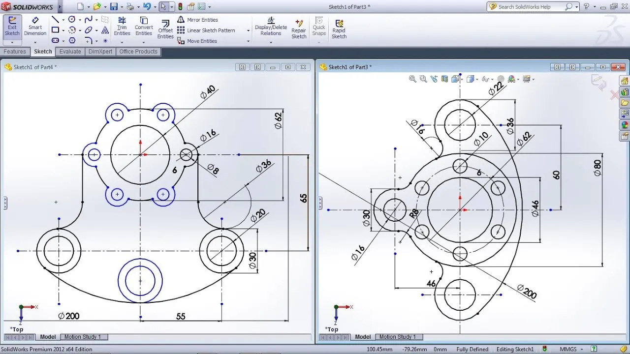
The sketching process is the first step in the SolidWorks workflow for product design. It involves creating 2D product design sketches using various tools such as lines, arcs, circles, rectangles, and splines. These sketches serve as a blueprint for creating 3D models of the product. The sketches can be modified as required to refine the product design. SolidWorks provides a range of tools for sketching, including the Smart Dimension tool, which enables designers to add dimensions to their sketches, making it easier to create accurate models.
In sketching, designers can use various techniques to make the process faster and more efficient. One such technique is using keyboard shortcuts. SolidWorks provides a range of keyboard shortcuts for various tools, making it easier for designers to access them quickly. Another technique is using sketch relations. Sketch relations enable designers to define the relationships between sketch entities, such as making two lines parallel or perpendicular to each other. This technique ensures that the sketch is accurate and reduces the time taken to make modifications to the sketch.
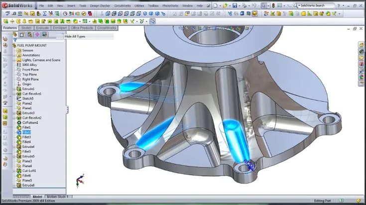
3D Modeling
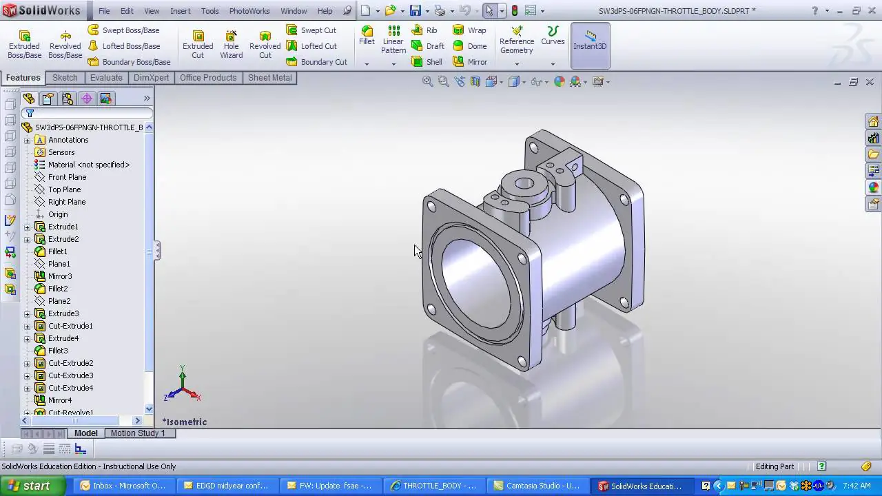
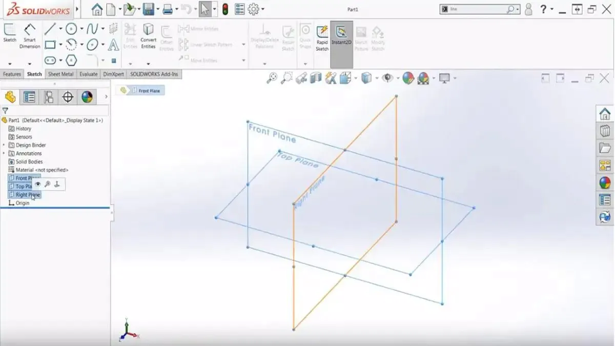
The next step in the SolidWorks workflow is 3D modeling. 3D modeling involves converting the 2D sketches into a 3D model, which is done by extruding or revolving the sketches, creating a 3D solid or surface model. SolidWorks provides a range of tools for 3D modeling, including the Extrude Boss/Base tool, the Revolve tool, and the Sweep tool. These tools enable designers to create complex geometries and surfaces for their product design.
One of the essential techniques used in 3D modeling is creating sketches on multiple planes. Creating sketches on multiple planes enables designers to create complex geometries and ensures that the 3D model is accurate. Another technique used in 3D modeling is the use of features. Features are tools that enable designers to create specific shapes or cuts on the 3D model. Features such as fillets, chamfers, and cuts are commonly used in 3D modeling to create a polished and accurate design.
Assembly Modeling
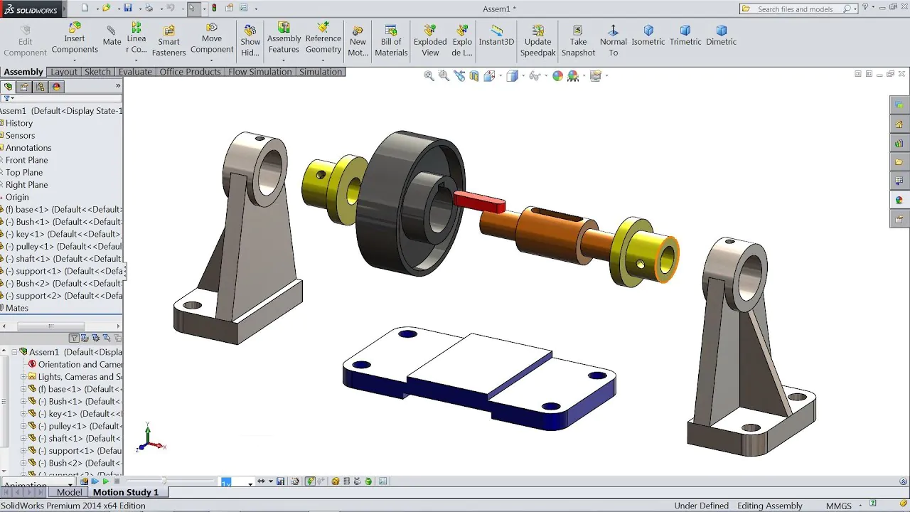
Assembly modeling is the process of combining multiple 3D models to create an assembly model of the product. This step involves creating a virtual representation of how the different components of the product fit together. SolidWorks provides a range of tools for assembly modeling, including the Mate tool, which enables designers to align and position components accurately. The Assembly Visualization tool lets designers view the assembly model differently, making it easier to analyze and modify the design.
One of the essential techniques used in assembly modeling is using subassemblies. Subassemblies are assemblies that are created within the main assembly. Subassemblies enable designers to create complex products and ensure the design is organized and easily modified. Another technique used in assembly modeling is the use of configurations. Configurations enable designers to create multiple product design variations within the same assembly. This technique ensures the design is flexible and can be modified as required.
Simulation
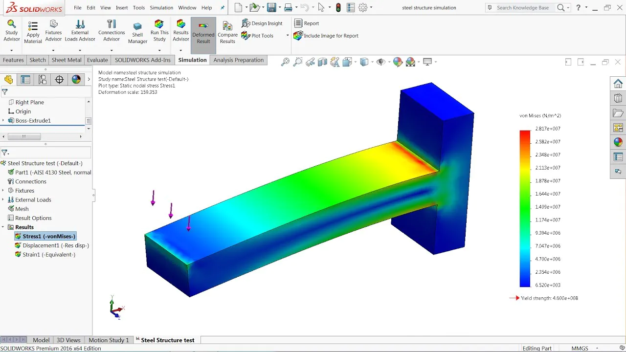
Simulation is a crucial step in the SolidWorks workflow for product design. It involves testing the product design in a virtual environment to meet the required performance standards. SolidWorks provides various simulation tools, including Finite Element Analysis (FEA) and Computational Fluid Dynamics (CFD). These tools enable designers to simulate the product’s performance under different conditions, identifying potential design flaws and making necessary modifications.
One of the essential techniques used in the simulation is using constraints. Constraints are conditions applied to the model to simulate how it behaves under different conditions. For example, a constraint could be applied to simulate the effect of gravity on the model. Another technique used in the simulation is the use of different materials. Different materials have different properties, and the simulation can be used to determine how the model behaves when different materials are used.
Renderings
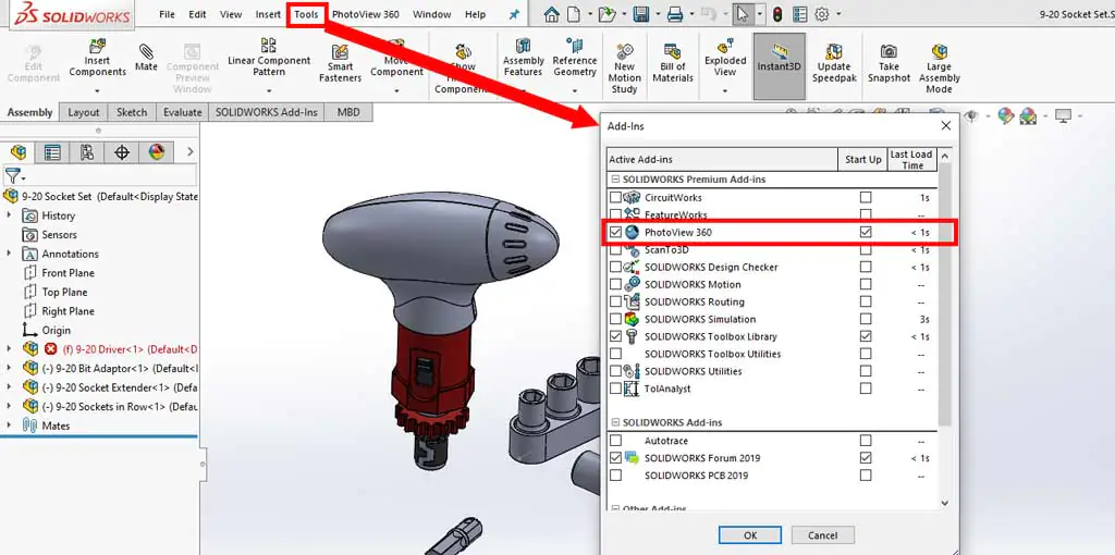
Once the product design is complete, the next step is creating renderings. Renderings are images that provide a realistic representation of the product design. SolidWorks provides various tools for creating renderings, including the PhotoView 360 tool. This tool enables designers to add textures, lighting, and backgrounds to their renderings, making them more realistic.
One of the essential techniques used in rendering is the use of materials. Materials are used to add texture and color to the product design. Different materials have different properties, and the choice of material can impact the final rendering. Another technique used in rendering is the use of lighting. Lighting can create different moods and effects in the rendering, making it more realistic.
Technical Documentation
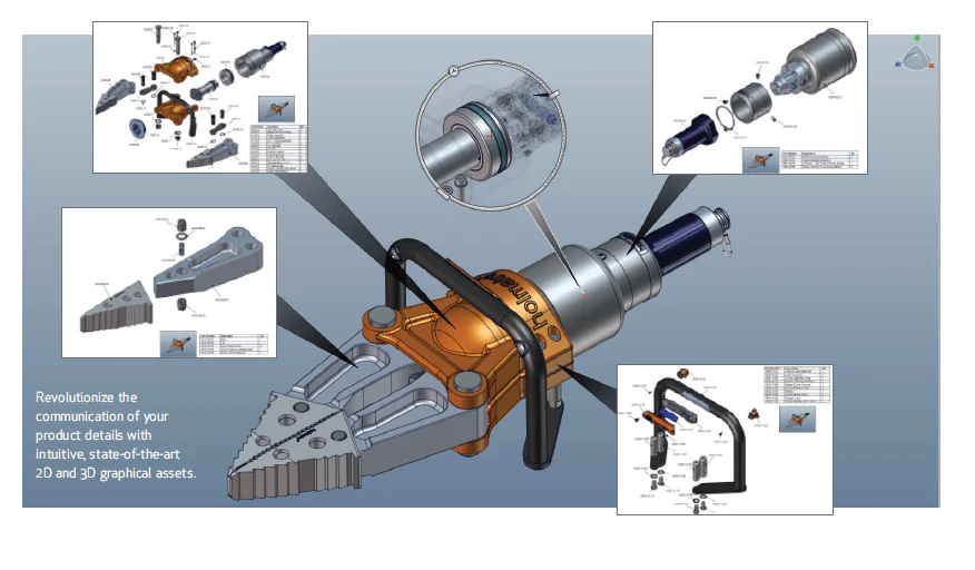
The final step in the SolidWorks workflow for product design is creating technical documentation. Technical documentation includes drawings and specifications that are used for manufacturing the product. SolidWorks provides various tools for creating technical documentation, including the Drawing tool. This tool enables designers to create detailed product drawings, including dimensions and tolerances.
One of the essential techniques used in technical documentation is using templates. Templates are pre-designed documents that can be used as a starting point for creating technical documentation. Using templates ensures that the documentation is consistent and easy to read. Another technique used in technical documentation is the use of annotations. Annotations are notes added to the drawing to provide additional information, such as material specifications or assembly instructions.
Collaboration
Collaboration is an essential part of the SolidWorks workflow for product design. SolidWorks provides various collaboration tools, including the PDM (Product Data Management) tool. This tool enables designers to manage the design data, ensuring that the latest version of the design is always available. The eDrawings tool enables designers to share the design data with other team members, allowing for collaboration and feedback.
One of the essential techniques used in collaboration is using version control. Version control ensures that the latest version of the design is always available and reduces the risk of errors or inconsistencies in the design. Another technique used in collaboration is the use of communication tools. Communication tools like chat and video conferencing enable team members to communicate effectively, ensuring the design is completed on time and to the required specifications.
Here are some important tips to follow for SolidWorks workflows:
Plan and organize your design process before starting.
Create a library of commonly used parts and features to save time.
Use design tables to automate repetitive tasks.
Use templates to maintain consistency across multiple designs.
Use simulation and analysis tools to optimize the design.
Collaborate with other team members using SolidWorks PDM (Product Data Management).
Keep your design files organized and well-structured.
Use SolidWorks macros to automate repetitive tasks and increase efficiency.
Keep up-to-date with new features and updates in SolidWorks.
Attend SolidWorks training courses to improve your skills and knowledge.
Conclusion
In brief, SolidWorks is a powerful CAD software solution that provides designers with a range of tools and workflows for product design. From sketching to technical documentation, SolidWorks offers a comprehensive set of tools that enable designers to create complex geometries, test the performance of their products, and produce high-quality renderings and technical documentation. Its collaboration tools make it easier for teams to work together on a project, ensuring efficient and effective design. SolidWorks is an essential tool for product design and is widely used across various industries, making it a valuable skill for designers.