How to use Tnkercad for 3D Modeling?
These days, prototypes can easily come to life on a computer screen, thanks to advancements in design and 3D CAD software. A new class of dynamically functioning apps has emerged as a result of modern processes, redefining what can be built in a given amount of time. Many flaws in outdated techniques have been fixed by 3D modeling, which has also improved functionality for design teams. Furthermore, a variety of 3D CAD software and advanced features in them also make 3D modeling an easy task for beginners as well. Well, in this post we will learn about one of the widely used software, TinkerCAD. We will discuss what is TinkerCAD and how we can use it for 3D modeling.
What is 3D modeling?
The process of developing a three-dimensional visualization of an object using computer applications is referred to as “3D modeling.” A 3D model of the object can be used to illustrate its size, shape, and texture. Both actual objects and plans that haven’t yet been created in practice can be turned into three-dimensional (3D) representations.
Ideas come to life with the help of modern 3D modeling. Designers have complete control over their models and can examine them from all sides. Teams are no longer limited to “flat” design, which greatly simplifies the process of evaluating changes without access to greater resources.
What is TinkerCAD?
TinkerCAD is an online bundle of Autodesk software tools that make it possible for complete newcomers to construct 3D models. Constructive solid geometry (CSG), the foundation of this CAD program, enables users to combine simpler elements to produce more complex models. Because of this, many people today use and love this 3D modeling program, especially instructors, youngsters, artists, and designers. The best part is that you can answer it for free with just an internet connection. Users of the software can design models that are suitable for 3D printing, which is a fantastic alternative for those who are new to the technology.
How to do 3D modeling with TinkerCAD?
Step 1: Understand the basics!
Since TinkerCAD is a web-based program, all that is required to get started is to create a free account on their website.
The main interface
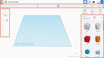
The primary interface of a project looks like this. The “Workplane,” where models are created and modified. The following components make up the interface:
Top toolbar: On the left, there are more general tools like “Copy,” “Paste,” and “Delete,” while on the right, there are design functions like “Group” and “Align.”
Navigation tools: These tools are used for simple orientation, such as zooming in and out. Note that the mouse wheel can also be used to control these particular tools.
Shape Panel: Includes all of the essential design elements, such as text and cubes, and spheres. (Exploring this box may be enjoyable because it has so many useful and sometimes configurable choices!)
Divide and Conquer
Let’s get started with the design as we are now familiar with TinkerCAD’s user interface.
A key idea in 3D modeling is the phrase “divide and conquer.” In general, it instructs us to separate a section into smaller shapes and work on each one separately. To make the final product, these components will ultimately be put together.
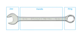
This method is extremely useful when simulating complicated real-world things. Let’s break down our wrench model into three fundamental components: the ring, the handle, and the jaw.
The next three processes will include designing these units, and the final step will involve putting them together. The wrench will be given some text in the sixth and final phase so that its size may be immediately determined.
Step 2: Design the ring
A solid disc with a hollow circular section in the middle, resembling a particularly thick washer, can be used to represent the wrench’s ring.
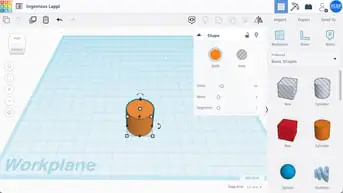
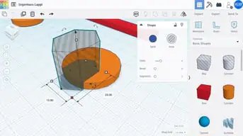
Drag a cylinder from the “Basic Shapes” panel to the workplane in order to start building this shape. The shape’s settings are displayed when you click on it under “Shape.” We won’t discuss them now, although learning about features like “Bevel” can be entertaining and helpful.
There are five white squares, or “handles,” on the cylinder when it is picked, four of which are on the shape’s bottom plane and one of which is above the cylinder.
Adjustment of dimensions
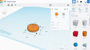
The cylinder’s length and breadth can be changed using the four handles in the bottom plane. Our ring should be 25 mm in diameter. The current measurements are shown in a tiny box when you click on a white square handle.
Either enter the values by clicking in the dimension box and pressing Enter or move the square handles until the cylinder has a length and breadth of 25 mm. TinkerCAD will automatically snap any dragging to the value that is displayed at the bottom right, for example, “1 mm.”
The cylinder’s height is adjusted by the lever above it. Just as you did with the length and the width, set the wrench’s height until it measures 4 mm.
Boolean operations and holes
We are moving forward. The solid disc has been completed; the only thing left is the center hole.
By subtracting elements to generate empty spaces and adding others to create new shapes, TinkerCAD runs on the Boolean design principle. (Keep in mind that these concepts are not used explicitly.)
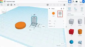
In order to make the circular hole in our ring for this phase, we will employ the subtraction operation. To begin, drag a different cylinder to the workplane and modify its length and breadth to 12.5 mm, which is the desired hole’s diameter.
Now here is the enjoyable part. Select this new cylinder, then click “Hole” in the window’s upper right corner. This instructs TinkerCAD to handle this form like it should be subtracted.
Alignment
The cylinder-shaped hole must next be placed in the center of the solid disc. We’ll make use of the alignment tool in the top toolbar for this.
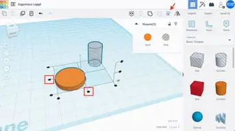
The objects that have to be aligned must first be chosen. After selecting the solid disc with the left mouse button, shift-click the cylinder hole. If you do this well, both objects should be chosen and highlighted at the same time.
In the toolbar at the top, click the “Align” button. On the workplane, you’ll see black handles in the shape of circles. To align the items along their central axes in both the X and Y dimensions, click on the bottom middle handles as indicated in the illustration below.
Grouping
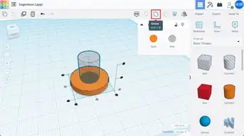
Press the “Group” button in the top toolbar after the two shapes are in alignment. There would be only one shape. In general, this tool puts two shapes together, but when one of the shapes is a hole, it also eliminates material. If everything went as planned, the final ring must be available.
The Ring
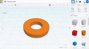
You can see an example of how the ring should be made in the image above.
This segment has provided us with a lot of new information. As an illustration, we are now able to size simple forms, make holes, align objects, and lastly group (or join) shapes.
Step 3: Designing the handle
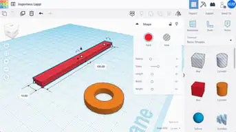
Probably the simplest portion of our wrench is the handle. Basically, all we need is a rectangle with the proper measurements.
Start by dragging and dropping a box into the workplane from the basic shapes panel. Either of the two methods outlined earlier should be used to set the box’s length and width to 100 and 10 mm, respectively. The height should then be fixed to 4 mm to match the ring.
Step 4: Designing the jaw
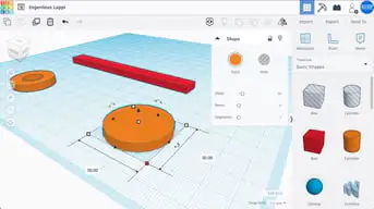
You may notice that designing the jaw should be pretty similar to designing the ring. The jaw is also like a circular disc that has a hexagonal hole carved out of it at an angle. Set the height of your disc to 4 mm and the diameter to 30 mm.
Polygon and hexagon
We’ll use the “Polygon” basic shape to construct the jaw-like structure. You can see that the polygon is by default a hexagonal shape by dragging it to the workplane. This is just what we require, but keep in mind that by modifying the relevant option in the Shape box, we may alter the polygon’s number of sides. All we have to do right now is make a hole out of our hexagon.
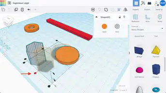
Alignment
Position the hexagon now. Let’s position the hexagon along one of the central axes of the disc once more by using the align tool. (To put it another way, center it in one direction only.) In the manner depicted above, select both shapes, click the “Align” button, and then click the black round handle.
We must insert the hexagon within the disc in order to maintain the separation between the two shapes. Hold Shift while dragging the hexagon to partially fit inside the disc in order to maintain the alignment we just accomplished. The hexagon needs to move straight ahead.
Dimension and group
We can set hexagon dimensions now that both shapes are in the right positions. We’ll make a 15 mm wrench, but feel free to experiment and use any size you like. (Take note that the remainder of the wrench might not be properly sized for values too close to 15 mm.)
Time to work some magic with subtraction! Press the “Group” button in the top menu after selecting both the disc and the hexagonal hole. You now have it. Bravo!
The jaw
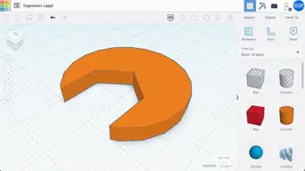
This is how the jaw should look, as shown in the image above. As previously said, you might have chosen to increase the hexagon’s number of sides depending on the type of wrench you’re constructing, which would have a somewhat different result. Time to put it all together now that we have the ring, handle, and jaw.
Step 5: Putting all together
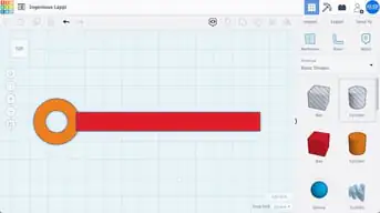
Let’s begin by putting the handle and the ring together. Just like in the previous stage, align both shapes in the “long” direction. After that, while still holding Shift, move the ring straight toward the handle. Utilizing the image above as a guide, make sure to slightly overlap the two shapes before moving on to grouping them.
This must combine the handle and the ring into a single piece. It now just has one color, rather than 2.
Rotate
![]()
First, left-click on the jaw to select it. Note the three curved handles with double arrows, in addition to the white handles. An angle value will appear when your mouse is above the one on the bottom (XY) plane.
You can manually enter a value or click and drag the handle around the shape to rotate the jaw. Here, a 45-degree counterclockwise rotation is required. (Tip: Holding Shift will restrict the rotations to which you may bend.)
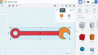
The jaw must now be merged to complete this stage. The process is basically the same as how we attached the handle and ring.
Align the two shapes first, and then while holding Shift, move the jaw in the direction of the wrench. Once more, place them so that they slightly overlap. In the end, group them!
Change color
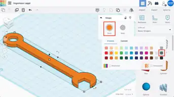
To do this, pick the finished wrench and press the “Solid” shape window button. There will be a wide range of colors on display. Let’s choose a deep grey.
There you have it, then! A flawless wrench for your workplane.
Step 6: Adding text
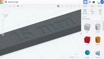
Could you tell each size apart simply by looking? Most likely not. Therefore, in this last step, we will immediately add the size information to the handle.
Find “Text” in the basic shapes panel and drag it to the workplane to accomplish this. Text works the same as any other shape, however, we can change its content. Make a hole there because we want to “carve” the text out of the handle.
Adjust and position
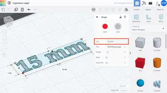
Click the “Text” area in the Shape window and enter “15 mm,” the wrench’s size, there. The shape will alter on its own. Now all that remains is to resize the text and merge it with the wrench. Make the necessary adjustments to make it 32 mm long and 7 mm wide.
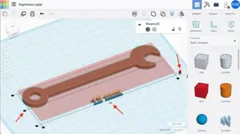
Let’s utilize the alignment tool once more to position the text above the handle. Choose both shapes, then click “Align.” We’ll choose the top round handle along the vertical axis as shown below since we want the text to “dig” into the top of the wrench.
The top surfaces of both shapes will be flush as a result. Click on the middle round handles in the XY plane to complete the text placement. Now that the shapes have been combined, all that is needed to do is to carve the words.
Lining up objects
The text’s bottom must be flush with the top of the handle if you want the embossed portion to emerge from the handle. Here’s a quick tip for arranging things in this way:
By clicking on the relevant surface and hitting “Workplane” (or “W” on your keyboard), you can shift the workplane temporarily. That would be the top of the wrench in this situation.
Choose the other object – the text for us – and press ‘D’. This will rest it on the temporary workplane.
By selecting “Workplane” and clicking away from any objects, you can end the temporary workplane. All items will stay in their current places.
Well, this was whole about 3D modeling with TinkerCAD. We hope, you have learned something from this post. So, go and construct your first 3D model.