How to use FreeCAD for 3D printing?
We all know the benefits of 3D modeling services are numerous. It saves time, enables you to make modifications to an object before its manufacturing, and reduces the number of prototypes, thus saving your cost. Also, a variety of different software is available for 3D modeling, however, in this post, we will discuss FreeCAD and how to use it for 3D printing.
What is FreeCAD?
FreeCAD is an open-source parametric 3D modeling program. It was created particularly to design real-world items. A specific kind of modeling known as parametric modeling involves using parameters to influence the geometry of the 3D objects you create. For instance, the three variables height, width, and length are used to influence the shape of a brick. These parameters are a component of the object in FreeCAD, just like they are in other parametric modelers, and they can still be changed at any moment after the object has been made.
FreeCAD is not intended to be used for a specific type of work or to create a specific type of thing. Instead, it supports a variety of applications and enables users to create models of all shapes and sizes, from tiny electronic components to objects that can be 3D printed all the way up to entire buildings. There are several specialized sets of tools and workflows available for each of these jobs.
How to use FreeCAD for 3D printing?
Step 1: Download the program
You don’t need to register or go through a lot of processes to download FreeCAD. Visit the FreeCAD website’s download page and click the download button. Choose your OS wisely as FreeCAD runs on Windows, MacOS, and Linux. Before beginning a new design, there are a few things to set up and become familiar with once the program has been downloaded.
Navigation
With several possible setups like other programs in terms of hotkeys and layout, FreeCAD lets you customize the navigation method.
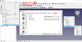
Right-click anywhere on the workspace and select “Navigation Style” (#1 in the image above) to change the navigation style. There are numerous options available. The best course of action is to leave it as is as we’ll be utilizing CAD to build the model.
Units
While using dimensions and when designing, units have an impact on your project, and they depend entirely on the task you’re working on (or your personal preference).
Check the units by selecting “Preferences > General > Units” (2) from the top menu under Edit. In this instance, we’ll use the metric system in mm, and we advise you to do the same if you’re modeling for 3D printing because slicing tools frequently use the same system.
Work benches
Finally, FreeCAD is set up using Workbenches, as we previously explained. We’ll move between the “Part Design” workbench and the “Part” workbench as we model. Find the workbench menu at the top of the toolbar (3) to change workbenches. The tools in the toolbar will change as you switch workbenches. By dragging and dropping the tools, you can also change their position. Some of the tools will be piled to the right of the screen and hidden, therefore we advise shifting them so you can view them all at once.
Step 2: Now sketch a base
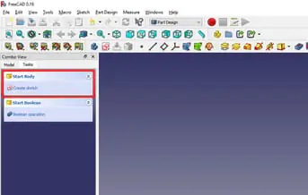
Modeling the bottom of the chest will be our first step. We’ll simply model a hollow box without a lid as the bottom of the chest (the lid comes later). To get started, go to the “Part Design” workbench, where the sketching tools are available.
You can create a body by selecting the Create a body option under the Combo View box to the left of the Viewport on the Tasks tab.
FreeCAD will prompt you to choose the plane in which you wish to design your model when you click “Create sketch.” Despite the fact that you can rotate this 3D model, it is still a good idea to select the plane in accordance with how you intend to create the component.
As we’ll be creating the lower portion of the chest, we’ll choose the XY plane, which is seen above. Choose this plane, then click “OK.”
Sketching Tools
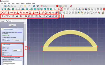
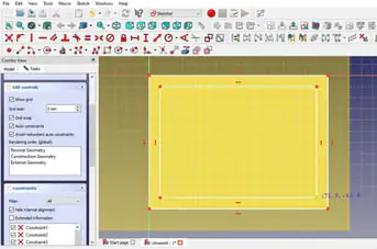
Drawing tools (1) and constraint tools (2) are used for sketching in FreeCAD because it is a parametric modeling program. By turning on the grid (3), you may make sketching simpler.
Select the Combo View option under the Tasks tab to display the grid.
There, under “Edit Controls,” there is a drop-down menu where you may select whether to display the grid, modify its dimensions, and enable grid snapping.
Since we’ll be working with roughly 100 mm on each side in this situation, 5 mm will serve as a good incremental space. We’ll set the grid spacing to 5 mm. You could opt to use smaller increments if you’re constructing a smaller model (e.g. a 10 x 10 mm model would work well with 1 mm spacing).
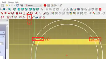
Draw the sketch
We’ll start by sketching a basic rectangle before moving on to the chest bottom.
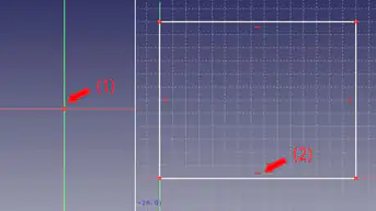
The origin point, which is represented by the red dot in the center of the screen (1), is where coordinate systems with respect to that point start.
We’ll start by outlining an 80 x 60 mm rectangle. Drawing will be easier because you can see the coordinates as you move.
When finished, the edges of the rectangle will have tiny, straight red lines inside them (2). These lines are constraints and show that there are both horizontal and vertical lines.
We can close the sketch since it is finished now.
Step 3: Extruding the base
The rectangle we now have is a 2D shape, so we must add height to it so that it may become a 3D shape and serve as the base of our box.
Go to the Combo View in the Model tab after closing the sketch to observe that a sketch has appeared on the hierarchy tree. By making one click on the sketch, it is selected. (Double-clicking an existing sketch will take you back to sketch mode where you can alter it.)
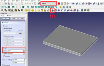
Find the Part workbench. The option to “Extrude from a selected sketch” is available here (1).
You may then modify other settings, such as the extrusion’s length, which we’ll set to 5 mm, in the Tasks tab.
Click OK. You will exit extrusion mode and the changes will be implemented.
Step 4: Create the hollow box
Since we are working in three dimensions now, we can transform our flat model into a hollow box.
Return to “Part Design”, choose the body, and then create a new sketch in the Tasks tab to design the walls of the chest.
To start, we’ll draw two rectangles in this sketch. There are two rectangles: one the same size as the first one and the other fitting inside it by 5 mm. This indicates that the chest’s walls will be 5 mm thick.
Select this sketch, return to “Part,” and then follow the directions in step 3 above to extrude the base to a length of 60 mm.
The wall thickness you specify at this point should be taken into consideration if you’re constructing your own model for 3D printing. Too thin walls might not even be printable or they might become too brittle to be useful. Be conscious that you shouldn’t extrude height more than your printer’s build volume.
Unifying solids
Since they are still separate bodies from the software’s perspective, the bottom and the walls appear to be separate shapes at this point. Although it won’t always influence a part’s ability to be printed, this can have significant effects on modeling. As there is no possibility to directly generate features inside the same body, FreeCAD must take a slightly longer way to resolve this.
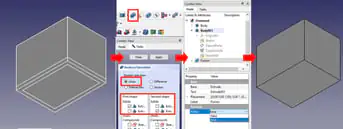
Select “Union” from the list of Boolean operations after choosing the two bodies from the model tree. They will no longer appear to overlap because they are now one piece, but you may still notice the distinct lines as if they were two bodies.
Select the Fusion element in the Model tree, which represents our fused model, to make those lines disappear. Change the Refine option in the properties to “true.” The program now displays and understands it as a single unified shape.
Step 5: Add a lid slot
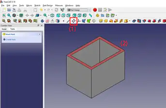
Making the slot for the cover is the next step. Since we will be changing the top of the model for this, we must establish a new reference plane there.
The creation of new reference geometries
Reference planes are known as “Datum planes” (1) in FreeCAD and are located in the Part Design workbench.
Make the top face (2) your datum plane by choosing it. Don’t choose anything else because we don’t need any further references in this scenario.
In order for the datum plane to contact the top face, set all offsets to zero.
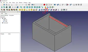
Extrude the cut
In FreeCAD, you extrude a shape and then use Boolean operations to subtract it from another body to cut into a body.
Choose the first body, then choose Tasks and add a new sketch. Choose the freshly built datum plane when FreeCAD prompts you to choose a plane.
On the datum plane, to create the slot for the lid of the chest, sketch a rectangle along one of the long walls, leaving 5 mm at either end.
Take the new rectangle to the “Part” workbench and extrude it 5 mm downward. With our chest base and the rectangle prism on top, we will now have two shapes.
Select both bodies, and then subtract the rectangular prism from the chest using the “Difference” Boolean operator.
Make sure “Refine” is set to true on the “Cut” feature that displays on the model tree.
Step 6: Adding details
Small holes will now be added to the interior of the chest so that the cover may be fitted. We will require new reference geometry to accomplish this.
Two additional datum planes should be created, one touching each of the chest’s shorter internal walls.
Make a 3 mm-diameter little circle in each one. (It could be beneficial to start off with a 0.5 mm grid spacing.)
The shape should be extruded to a depth of 2 mm. This leaves 3 mm of the wall once the shape has been cut off. As we previously indicated, if you intend to 3D print your model, you shouldn’t cut too deeply because that will result in too thin walls.
Use the Boolean tool to cut the circles.
A fillet will be the final component we include. For this, while still on the “Part” workbench, add a fillet to the edge as indicated in the above image by using the fillet tool (1) with a 2-mm radius.
Step 7: Create the cover
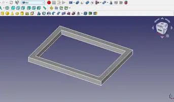
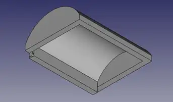
We’ll design a new part to make the cover.
Create a hollow rectangle on the XY-plane and extrude it to be 5 mm high using everything you’ve learned so far. To match the chest, the interior rectangle will be 70 x 50 mm and the outer will be 80 × 60 mm (5 mm smaller in all directions). The outcome is represented in the above picture.
Create a new datum plane on one of the shorter side faces.
Using constraints
To give the cover a round form, let’s now draw a circle. You can see the steps that have been performed at this point in the figure above, so you know what you should aim for.
Make a circle of any radius by choosing the middle at a distance of 10 mm from the solid’s bottom (30 mm from each side).
In the rectangle’s upper right corner, add a point. A constraint that fixes a point to an object will be used. The circle’s radius will coincide as a result, causing it to instantly snap to the rectangle’s corner.
From the same point, draw a second circle to provide the cover thickness.
Now add one more point inside the cover, touch the inside wall and utilize the constraint to create another circle snap to this point.
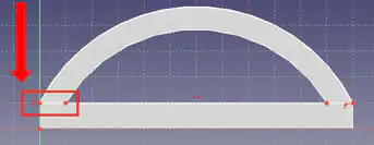
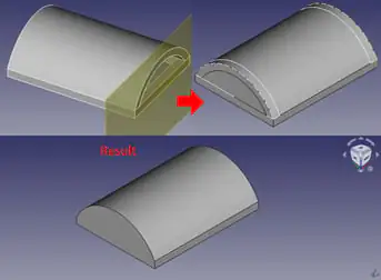
Trimming
We’ll simply draw lines where the circle has to stop (1) to limit the circle’s extension because we only need a fraction of it. This correlates to the left and bottom edges of the visible rectangle, as seen above.
We’ll use the trim tool to further trim the circle (2).
Extrude the cover
The sketch should be copied and pasted before continuing because it will ultimately save us time.
The curving drawing should be extruded until it reaches the opposite side of the model (80 mm).
Now we’re going to make a few minor adjustments to the sketch that was copied. Remove the interior of the illustration, leaving only the exterior.
To finish the base’s bottom, draw a line. As a result, this component has a solid shape rather than a hollow one. The drawing that resulted is displayed in the picture above.
By establishing a new datum plane, we will extrude this 5 mm and do the same on the opposite side. This constitutes the cover’s side walls.
After completing each component, combine the results using a Boolean operator to complete the lid.
Step 8: Add details to the cover
The methods from step 5 are now repeated, but this time for the cover. This time, we’ll extrude the rectangle by 3 mm, but rather than removing it, we’ll merge it with another rectangle to form a single body.
Create the cylinders that will snap-fit to the circles made in step 5 as the second detail we’ll add. These circles, which should have a diameter of 2 mm and a length of 1 mm, sit on either end of the rectangular prism connected to the cover. Remember that we want these cylinders to stick from the cover, so use the Boolean operator to combine rather than cut.
This is a good time to provide additional details about these measurements and how the 3D printing process affects them.
To accommodate the printer’s tolerance and to permit the parts to move, the cylinders attached to the cover are both shorter and wider than the holes in the box. The extruded and cut-away sections wouldn’t likely snap together and would be challenging to move and utilize if they were created with the same dimensions.
Your slicer settings ultimately determine the outcome of your print, however, a typical setting to utilize is a 0.2 mm layer height. This setting will require five lines of filament to extend to 1 mm in length. Any fewer filament lines might not be able to withstand the wear and tear of installing and using the cover. However, because of the tight fit, anything longer than 1 mm could break as you attempted to snap it into place.
Well, this was all about FreeCAD and how to use it for 3D printing. I hope you learned something from this post, hope will make your 3D model with the help of this tutorial.