How to Create Custom Materials & Shaders for Realistic Product Looks
The development of realistic materials and shaders is a vital step in the development of realistic 3D product renders. Most product models are flat, too glossy or aesthetically inconsistent due to the default shaders or arbitrary settings and missing the definition of surface properties such as roughness, reflection and edge wear.
Precise physical control of base color, reflectivity, variation of roughness, normal detail and micro-surface effects can be controlled using custom materials and shaders. With baked texture data, combined with procedural inputs and stacked shader configurations, artists are able to have consistent, repeatable and production ready materials across a number of products.
This guide includes a step wise workflow in blender with emphasis being on technical precision and pipeline preparation. Each step of material analysis to shader configuration, layering and lighting validation is arranged in such a way that it gives predictable and high quality output to the e-commerce visualization, real time engines, or cinematic rendering.
Step 1: Analyze Real-World Material Behavior
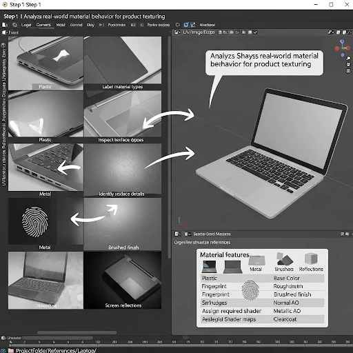
First, collect high-quality product images (front, side, and close-ups) of the item, such as a laptop, and store them in a dedicated folder (e.g., ProjectFolder/References/Laptop/). Examples of images could include References/Laptop/Laptop_Plastic_01.jpg, References/Laptop/Laptop_Metal_01.jpg, and References/Laptop/Laptop_Screen_01.jpg. Next, label each image by its corresponding material type, such as Laptop_Plastic, Laptop_Metal, or Laptop_Screen.
This labeling will make it easier to map them to shader channels later. Afterward, examine the surface details of each image by opening them in Blender’s Image Editor or any other image viewer. Zoom in closely on the edges, corners, and flat surfaces, and identify visible patterns such as texture (e.g., grain, brushed metal, fingerprints, smudges) and the level of finish (e.g., reflecting or matte, scratched). Record these details in a simple table with columns for Material, Feature Type, and Location, like Plastic | Fingerprint | Top Cover, Metal | Brushed | Side Panel, and Screen | Reflection | Display.
Then, create a checklist for each material to determine which maps are needed for the shader: Base Color (required), Roughness (required), Normal Map (optional, for surface details), AO Map (optional), Metallic (if the material is metal), and Clearcoat (optional, for polished surfaces). Keep this checklist ready for Step 2 when you begin creating nodes in Blender. Finally, prepare for procedural shader work by opening Blender and loading the reference images in the UV/Image Editor. Arrange your workspace with the reference photo on the left and the 3D model viewport on the right, so you can easily compare and test materials with shaders as you build.
Step 2: Set Up Physically Correct Base Shader in Blender
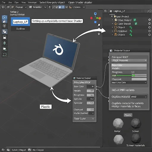
First, open your Blender project by launching Blender and going to File → Open, then select the .blend file where the laptop object is located. To see all of the objects, switch to the Layout workspace from the top bar. In the Outliner (top-right), find your laptop low-poly object (e.g., Laptop_LP) and click on the object’s name to select it. You can press the Numpad to zoom in on the object in the 3D Viewport. Next, open the Shader Editor by switching one of the panels to it. Click on Editor Type in the top-left corner and choose Shader Editor. Ensure that your low-poly object is selected, and click its material slot to either view or create a material. If no material is assigned, click on New, assign the material, and name it Laptop_BaseMat. Ensure that the Principled BSDF node is connected, then set the Base Color to a neutral gray (0.8, 0.8, 0.8) to start. For the Metallic setting, set it to 0 for plastic parts and 1 for metal parts (like chainstay and screws). Set the Specular to 0.5 and Roughness to 0.3, adjusting further as needed to match the reference. Set Clearcoat to 0 for matte surfaces, or increase it for glossy/polished surfaces.
Verify that the material node is plugged into the Material Output, and make sure the color space is correct: Base Color should be in sRGB, while Roughness, Metallic, and Normal should be set to Non-Color Data. For multiple laptop materials, duplicate the shader for each material variant, such as Laptop_PlasticMat for the plastic top, Laptop_MetalMat for the metal sides, and Laptop_ScreenMat for the screen. To do this, click Material > Duplicate, rename the material, and assign it to the corresponding faces through Edit Mode by selecting the faces and assigning the material. Finally, save your Blender project by clicking File → Save, and keep the .blend file organized in your project folder, such as ProjectFolder/Blender/Laptop_BaseShader.blend.
Step 3: Integrate Baked Textures & Procedural Maps
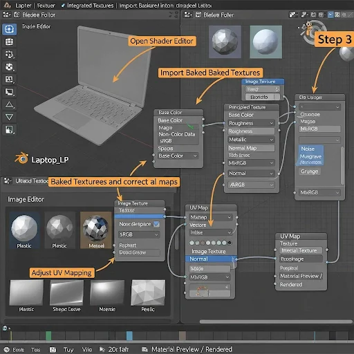
First, open the Shader Editor by locating your low-poly laptop (e.g., Laptop_LP) in the Outliner. Change one of the panels to the Shader Editor. Make sure the correct material is selected: Laptop_PlasticMat for the plastic parts, Laptop_MetalMat for the metal parts, and Laptop_ScreenMat for the screen. Then, import the baked texture maps by pressing Shift + A → Texture → Image Texture. Click Open and navigate to your baked textures folder (e.g., ProjectFolder/Textures/Laptop/). Select the correct map for each material, such as Laptop_Plastic_BaseColor_2K.png, Laptop_Plastic_Roughness_2K.png, and Laptop_Metal_Normal_2K.png, and repeat this for each material type and map.
Next, assign the texture maps to the shader nodes. For the Base Color, link the Image Texture to the Base Color input on the Principled BSDF node. For Roughness, use the Image Texture (set as Non-Color Data) and link it to the Roughness input. For Metalness, link the Image Texture to the Metallic Value input, also set as Non-Color Data. For the Normal Map, add a Normal Map Node (Shift + A → Vector → Normal Map), then link the Image Texture (set as Non-Color Data) to the Normal Map node, and connect that to the Normal input on the Principled BSDF. Set the image node settings for Roughness, Metallic, and Normal maps to Non-Color Data. For the Base Color maps, leave the color space as sRGB.
To add micro-details, use a Noise Texture, Musgrave, or Grunge Map, combining them with the roughness or color using MixRGB → Multiply, and connect this to the Roughness input for extra randomness. Ensure that the correct UV map is selected in the Image Texture node. If you have multiple UV setups, use a UV Map Node and connect it to the Vector input of the Image Texture. Avoid overlapping islands for even baking. Finally, switch the viewport to Material Preview or Rendered (Eevee/Cycles) mode to compare the material to the references in the Image Editor. Check for edge highlights, reflection behavior, roughness variation, and the fidelity of normal details. After adjustments, save the shader by clicking File → Save, and organize your file structure, such as ProjectFolder/Blender/Laptop_CustomShader.blend.
Step 4: Build Edge Wear & Detail Response
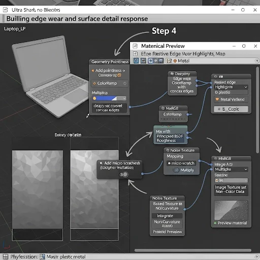
First, open the Shader Editor by selecting your low-poly Laptop object (e.g., Laptop_LP) from the Outliner. Then, change one of the panels to the Shader Editor. Make sure the correct material is active: Laptop_PlasticMat for the plastic parts and Laptop_MetalMat for the metal parts. Next, add an Edge Detection node by going to Add → Input → Geometry → Pointiness. The Pointiness node calculates whether an edge is convex or concave, which will be helpful for simulating edge wear. Add a ColorRamp node (Add → Converter → ColorRamp) and connect the Pointiness node to the Factor input of the ColorRamp. Adjust the ColorRamp so that black represents no wear and white represents full wear.
After that, mix the edge wear with the roughness by adding a MixRGB node (Add → MixRGB), setting the blend mode to Multiply. Link your Base Roughness Map to Color1 and the Edge Wear Factor (from the ColorRamp) to Color2. Connect the output of the MixRGB node to the Roughness input of the Principled BSDF node. To add micro-scratch details, go to Add → Texture → Mapping Node, and connect it to a Noise Texture. Then, add a Math Node (Add → Math → Multiply or Power) and connect the Noise output to the Roughness input for added detail. To integrate ambient occlusion (AO) or curvature maps, open your baked AO or Curvature Map using an Image Texture node (set to Non-Color).
Add a MixRGB node (set to Multiply) and plug it into the Roughness input. After these adjustments, preview the shader in Material Preview mode by rotating the laptop model. Check for the correct edge highlights, proper reflection behavior on metal edges, and subtle variation on the plastic parts. Finally, adjust the ColorRamp sliders to control the intensity of edge wear and scale the Noise texture if needed to match the reference image. Once satisfied, save your shader by going to File → Save. The suggested file path for saving is ProjectFolder/Blender/Laptop_CustomShader_EdgeWear.blend.
Step 5: Layer Additional Materials & Fine-Tune Realism
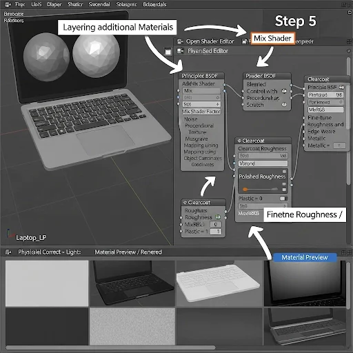
Start by opening the Shader Editor and selecting your low-poly laptop object (e.g., Laptop_LP) from the Outliner. Change one of the panels to the Shader Editor and make sure the active material is either Laptop_PlasticMat or Laptop_MetalMat (depending on which material you’re working on). Next, add layered materials using a Mix Shader node by pressing Shift + A → Shader → Mix Shader. Connect the first Principled BSDF node to Shader1 for the base material, and then add a new Principled BSDF for Shader2, which will be used for the second material (such as a glossy coating or surface scratches). You can control the blend between the two materials with the Fac input, where black will display only the base material, and white will show only the secondary effect.
To integrate a procedural layer for wear or reflection, use a Noise, Voronoi, or Musgrave Texture node and map it to the Factor input of the Mix Shader. Hook up your Mapping node to the texture coordinates (set to Object) so you can control the layer more precisely. This layer can model random surface deformations or coating abrasion. For polished surfaces, add a Clearcoat layer by adjusting the Clearcoat value in the Principled BSDF to a range of 0.2–0.5, depending on your reference. If needed, you can also add Clearcoat Roughness by using either an image texture or a procedural map. Fine-tune the roughness and metallic values by baking a Roughness map, mixing it with some procedural noise, and then connecting it to the Roughness input of the Principled BSDF. Adjust the Metallic value based on the material: set it to 0 for plastic parts and 1 for aluminum sides to make the material react properly to light.
Finally, check the shader in Material Preview or Rendered View mode by rotating the model and adjusting the viewport lighting. Verify that the layer transitions are seamless, the edge wear and microdetails blend naturally, and that reflections, glossiness, and roughness react realistically. Once you’re satisfied with the results, save your shader by going to File → Save. The recommended save path is ProjectFolder/Blender/Laptop_CustomShader_Full.blend.
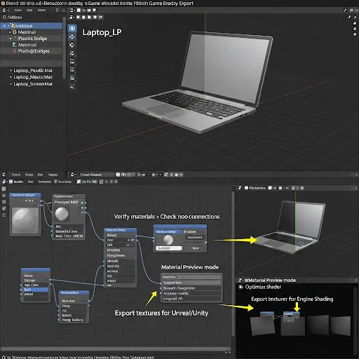
Step 6: Prepare Shader for Rendering or Engine Export
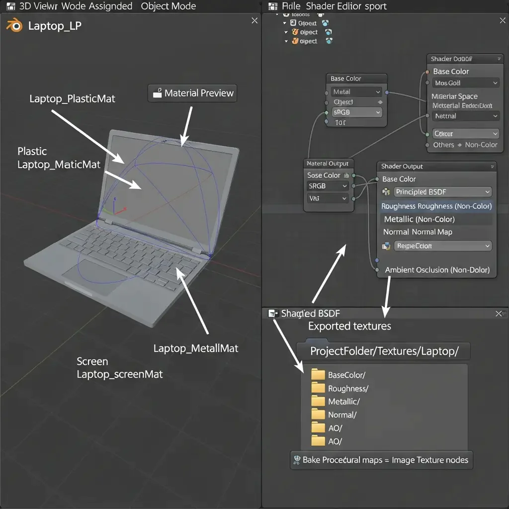
Start by finalizing the material assignments in Blender. Select your low-poly laptop object (e.g., Laptop_LP) from the Outliner, and check that all materials are correctly assigned: Laptop_PlasticMat for plastic parts, Laptop_MetalMat for metal parts, and Laptop_ScreenMat for the screen. Next, open the Shader Editor and confirm that all Principled BSDF nodes are correctly connected to the Material Output. Check that your baked textures and procedural nodes are connected as follows: Base Color to the Base Color input, Roughness to the Roughness input (set to Non-Color), Metallic to the Metallic input (set to Non-Color), and Normal to the Normal Map input.
Ensure the color space is set correctly for each map. Set the Base Color to sRGB, and for Roughness, Metallic, Normal, and AO maps, set them to Non-Color. This will ensure the materials render correctly in game engines like Unreal, Unity, or even in Cycles. To optimize your shader for performance, try using procedural nodes where possible to reduce the overall node count. If you are using procedural maps for multiple assets, bake them into image textures and save them in your project folder. This will reduce the load on your GPU when rendering. After optimizing, test the shader in Material Preview mode. Rotate the laptop and check for proper edge wear, rough surfaces, metallic reflections, and gloss. Ensure that the screen and metal edges exhibit correct reflection behavior, and that the AO effect integrates seamlessly.
When you’re satisfied with the result, you can export the shader for game engines like Unreal or Unity. Export the textures for Base Color, Roughness, Metallic, Normal, and AO, ensuring the Normal Map is set to Non-Color and the Base Color is set to sRGB. For proper organization, create folders within your project directory for each texture type, such as ProjectFolder/Textures/Laptop/BaseColor/, Roughness/, Metallic/, Normal/, and AO/. Finally, save the final Blender project by going to File → Save As and naming it Laptop_FinalShader.blend.
Step 7: Quality Check & Troubleshooting
First, open the Image Editor in Blender by selecting the low-poly laptop object (e.g., Laptop_LP) in the Outliner. Change one of the panels to the Image Editor (top-left → Editor Type → Image Editor). Click on Image → Open, and browse for your texture files in the folder ProjectFolder/Textures/Laptop/. Open each of the baked maps, such as Laptop_Plastic_BaseColor_2K.png, Laptop_Metal_Normal_2K.png, and Laptop_Screen_Roughness_2K.png.
Next, verify each map. For the Base Color map, check that the colors match your reference and ensure there are no black or white spots, speckling, or bare areas. For the Roughness map, make sure the highlights are where they should be, and there are no large, flat, uniform regions unless intended. For the Normal Map, inspect the surface details for any reversed or corrupted areas. For the AO map, ensure the shadowing in corners and tight spaces is correct and that there are no holes in the shadow details.
Then, check the material assignments by going to the 3D Viewport and switching to Material Preview mode. Select each part of the laptop (plastic, metal, screen) one by one and check their respective properties. For the plastic, verify rough reflections and roughness; for the metal, check for metallic shine and edge usage; and for the screen, confirm glossy, uniform reflections. Test the shader under different lighting by switching the Viewport Shading to Rendered mode and rotating the model 360°. Observe the edge highlights, specular reflections, micro-scratch details, and the integration of the AO map.
If you encounter any issues, address them as follows: If the Base Color is missing, check for a missing Image Texture node and assign the correct image. If the Normal map is corrupted, ensure the Color Space is set to Non-Color, and consider re-baking if necessary. If the Roughness or Metallic values are wrong, double-check the MixRGB or any procedural layers and make sure they are connected to the correct output. If the edges look too flat, adjust the Pointiness and ColorRamp settings from Step 4. If necessary, re-bake or update the nodes, and use a valid Image Texture node. To re-bake, go to the Render Properties tab, click Bake, and save the image by selecting Image → Save As, and then save it in the ProjectFolder/Textures/Laptop/ folder.
Finally, preview the shader in your target engine (Unreal or Unity). Apply the materials to the laptop model in the engine and verify that the metallic/roughness response, AO, normal maps, and screen reflections behave as expected. Once everything is verified and working correctly, save the Blender project by going to File → Save. You may also want to create a backup of the file as Laptop_ValidatedShader.blend.
Conclusion
To make the custom materials and shaders in Blender look realistic, precision, careful arrangement, and validation is needed. A step-by-step workflow, assigning baked textures, combining procedural maps, creating edge wear, overlaying materials, preparing engine export, etc. will make sure that you have correct reflections, roughness response, and micro-detailed product models.
This technical solution is used to do away with guess-work, minimize error and generate PBR shaders that are production ready and can be used reliably across renders, real-time engines, and visualization pipelines. By performing these actions, material creation moves beyond a trial-and-error process and becomes scalable, reliable, and of high quality, which is professional enough to use in creating 3D products.