How to Build a Unified Asset Pipeline from CAD to Marketing 3D Models
Teams often struggle when moving CAD data into marketing workflows. CAD files are heavy, complex, and not optimized for rendering or interactive use, which leads to errors, slowdowns, and repeated rework. Marketing teams frequently spend extra time cleaning models or recreating assets, while engineers worry about version mismatches and losing design accuracy.
Understanding how to build a unified asset pipeline from CAD to marketing 3D models helps solve these issues. This pipeline transforms detailed engineering CAD data into lightweight, accurate, and reusable marketing assets while maintaining a single source of truth. By connecting CAD cleanup, mesh optimization, UV mapping, material creation, and final export into a structured workflow, teams reduce errors, save time, and deliver high-quality 3D content consistently across all marketing platforms.
Step 1: Define and Lock the Master CAD Source
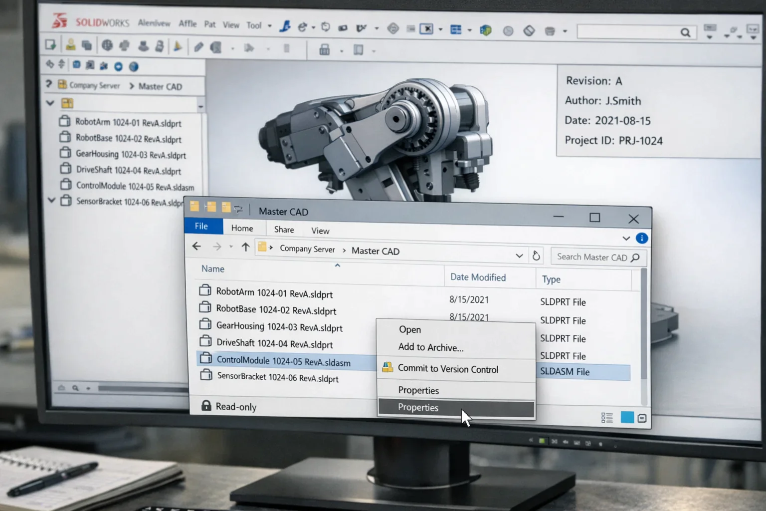
Start your CAD software (e.g., SolidWorks, Creo, CATI, A, or Fusion 360) and open the project folder with all CAD files. Check the revision number or the date of revision of every part or assembly. Transfer these files to a special folder of your company server or PLM system called Master CAD. You can right-click the folder and change it to Read-Only, as this will not allow the marketing and visualization users to accidentally make changes. Add a standardized naming convention to all files, i.e., ProductName partnumber revA.sldprt, to allow consistency and prevent duplication of files. Commit every file to your version-control system or PLM, allowing them to be accessed by members of the team, but overwrites by team members should be prohibited. Ensure that all files contain all the metadata, such as author, version number, date, and project ID. These steps will help you to have one source of truth, have version control, and offer all the downstream teams a stable base of CAD to build marketing-ready 3D assets.
Step 2: Clean and Defeature CAD Models
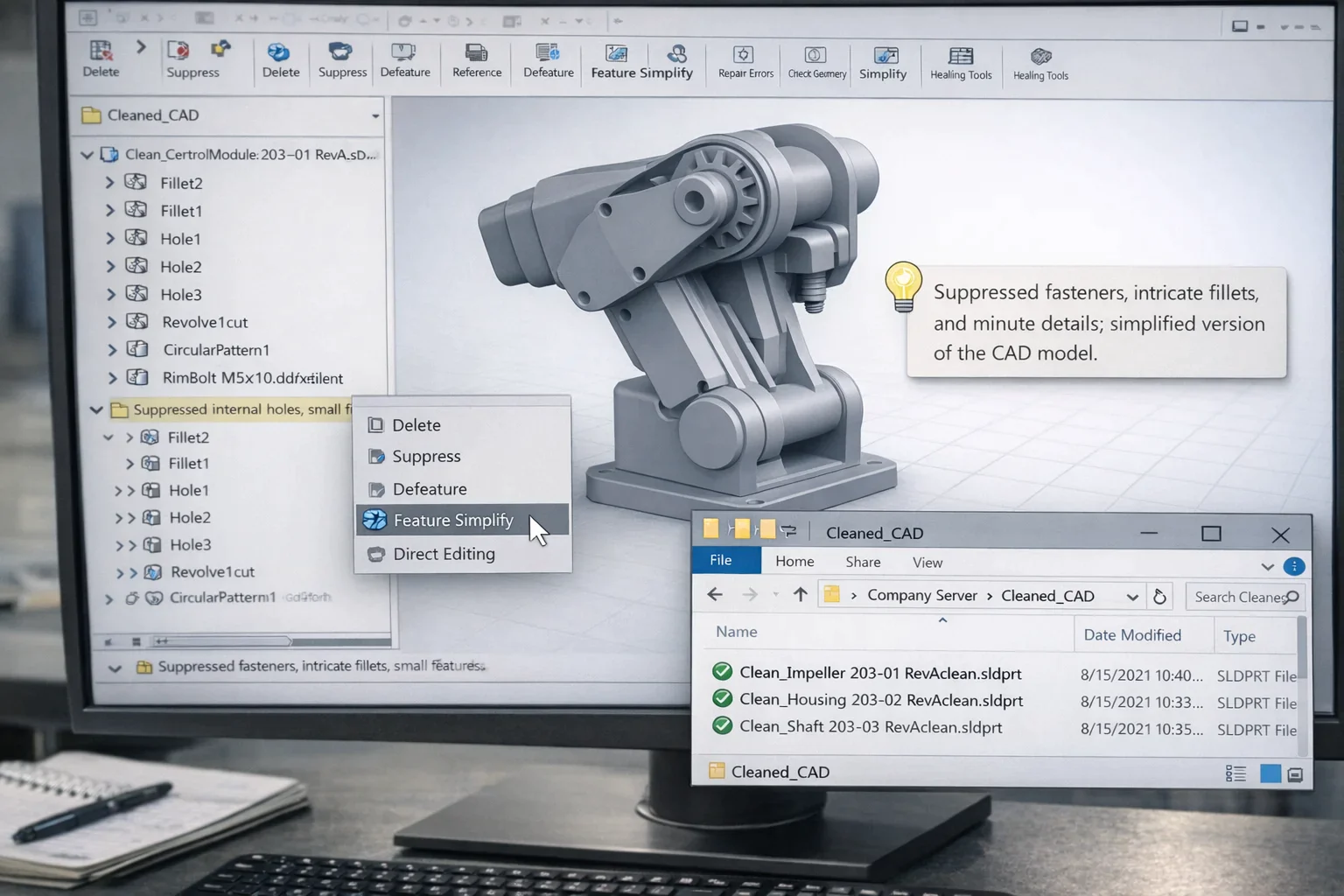
In your CAD system, open every master CAD file and look into the assembly of your CAD and look at any non-visible or manufacturing-only components (a fastener, internal support, or small holes) made in the assembly that do not contribute to the look of the product. Either delete them using the Delete, Suppress, or Hide buttons or remove them without leaving the geometry that will ultimately appear in marketing assets. Look for intricate fillets, small holes, or minute details that increase the file size and render slowly; reduce them with Feature Simplify, Defeature, or Direct Editing tools. Check Every Surface: Check every surface that is not a manifold or has errors and repair using Repair, Check Geometry, or Heal. After cleaning, put the simplified files into a special “Cleaned_CAD” folder, keeping the original naming system and adding a suffix like the one below to make it clear (ex, ProductNamePartNumberRevAclean.sldprt). Ensure that the design intent and integrity of the files being cleaned are maintained and that the files being cleaned are still fully compatible with other downstream 3D software. This is done to make the CAD models lightweight, error-free, and convertible to marketing-ready 3Ds.
Step 3: Export CAD to Neutral 3D Formats
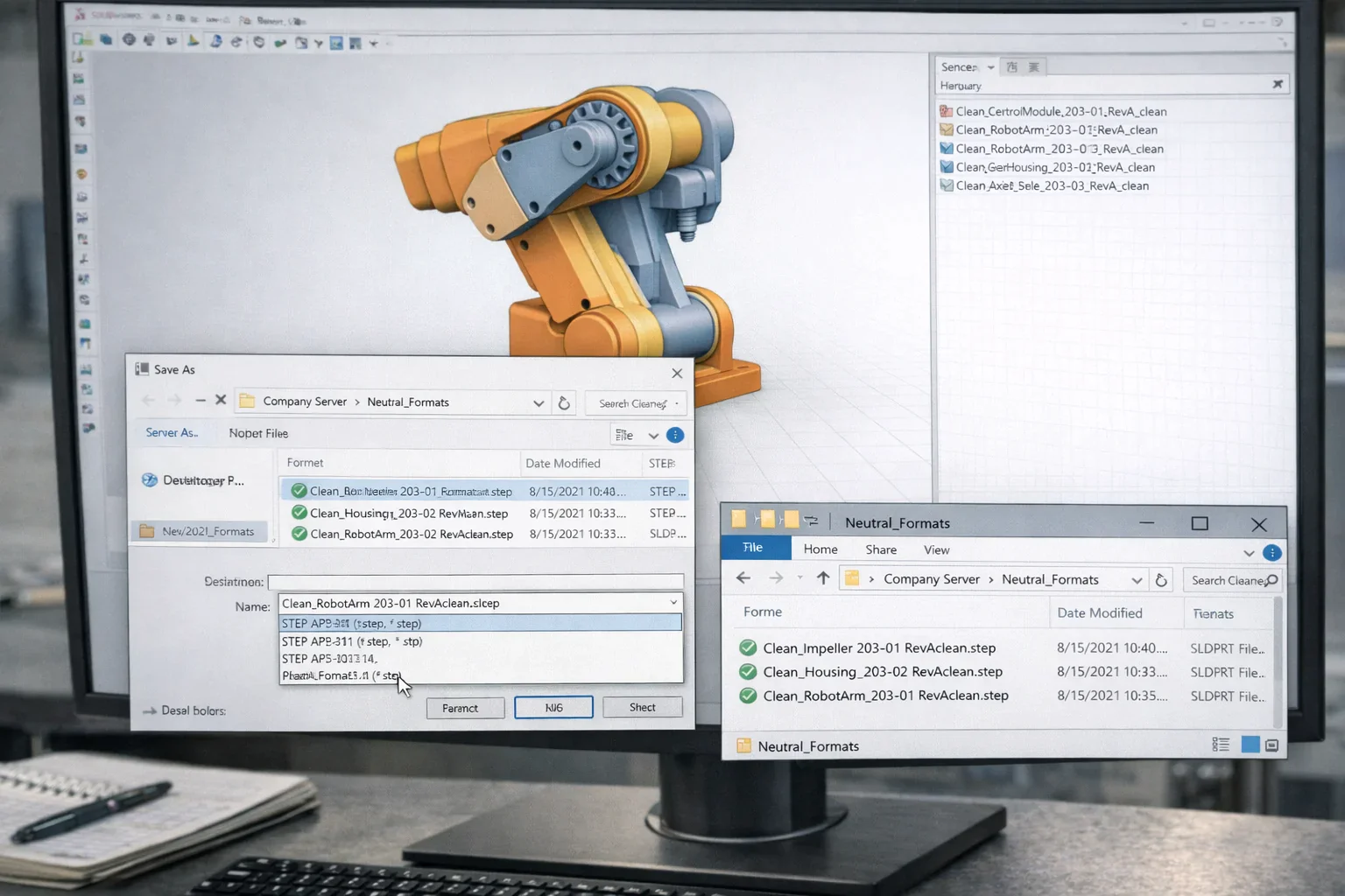
You should open every one of your clean CAD files in your CAD system and go to the File save as or Export menu. Choose an impartial 3D expression like STEP (.step / .stp), IGES (.iges / .igs), or Parasolid (.x_t / .x_b) based upon subsequent software compatibility. Select export options that maintain the structure of assembly, units, and geometric precision, which will ensure all parts and sub-assemblies are present. In the case of assemblies, make the export an assembly option so that the hierarchy is not lost, and the export of the hidden or suppressed components should be disabled. Change the output folder to a special (Neutral_Formats) folder and keep using the same file naming convention, but add an ending suffix like step or iges (eg ProductName_PartnumberRevA)step.stp. Once the file is exported, load a sample file into the target 3D application, and ensure that the geometry is correct and all the surfaces, normals, and part associations are accurate. Through such actions, you develop a universal and compatible framework of CAD files that can be the stable connector between engineering information and market-compatible 3D representations.
Step 4: Import CAD into 3D Production Tools
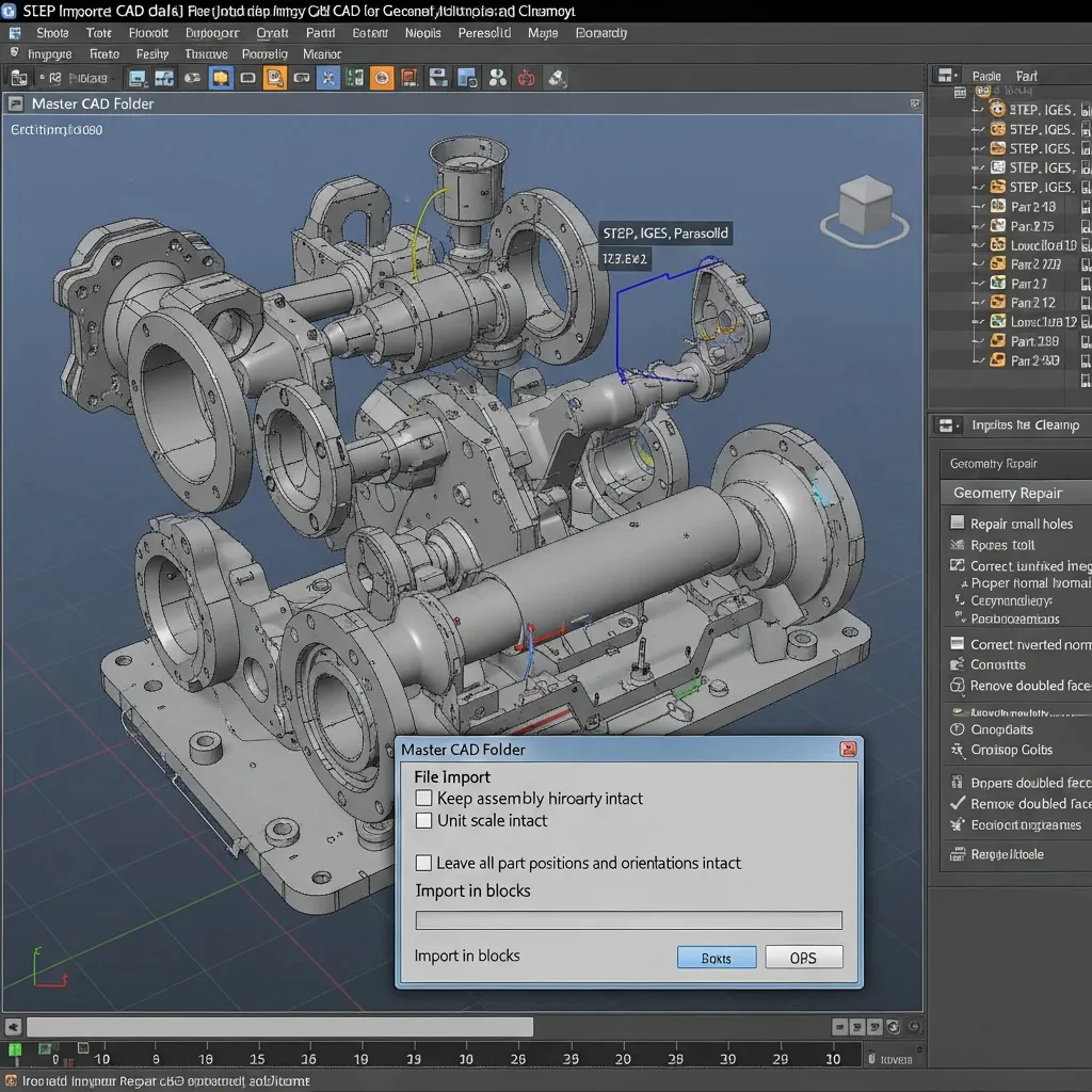
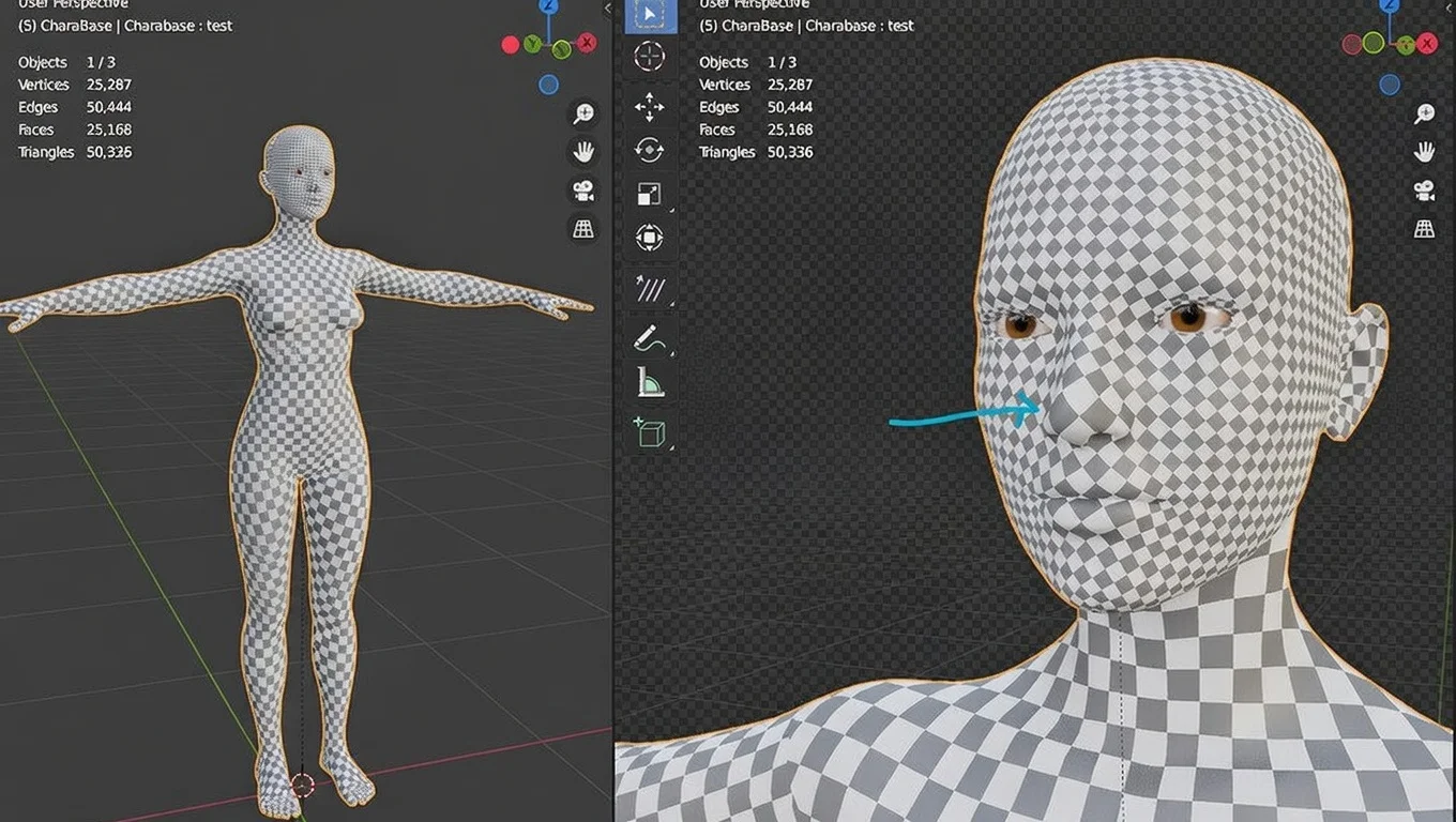
Open your 3D production software (e.g., Blender, 3ds Max, Maya, or Cinema 4D) and create a new project or scene. Go to the File Import menu and choose the neutral CAD files that were exported in step 3 (STEP, IGES, or Parasolid). Under the import settings, have an option to keep assembly hierarchy intact, unit scale intact, and to leave all part positions and orientations intact. In a large assembly, it is better to import in blocks so as to keep track of the memory used and avoid crashes. After being imported, examine every part to verify that surfaces are not damaged, normals are proper, and that there is no missing geometry. In case of errors, repair or geometry cleanup tools of the software can be used to correct small holes, inverted normals, and doubled faces. Arrange the imported parts on the scene by giving layers or groups different names according to the part number,r as in the Master CAD folder. The process guarantees the accurate portrayal of all the CAD geometry into the 3D production environment and is set to undergo polygon conversion, optimization, and additional asset preparation.
Step 5: Convert Geometry to Optimized Meshes
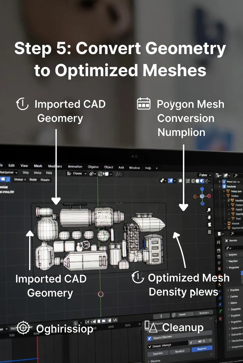
Imported CAD parts or assemblies. Each part or assembly utilized in your 3D production software is selected, and NURBS or CAD surfaces are converted to polygon meshes with the software’s Convert to Mesh or Triangulate feature. Change the mesh density to trade detail against performance-high where the object is visible and low where the object is not visible or flat. Use polygon reduction or decimation utilities to minimize unwarranted geometry without changing the overall shape. Check every mesh to ensure that it has no non-manifold edges, reversed normals, or duplicated faces, and fix any problems with Mesh Cleanup, Merge Vertices, or Recalculate Normals. This is maintained by preserving the original part hierarchy, that is, by grouping or parenting meshes based on the CAD assembly structure. Store all the optimized meshes in a special folder named Optimized_ Mesh, with the same file naming structure and a suffix, e.g., mesh appended (e.g. ProductName_PartNumber_RevA_ mesh. obj). The final product of accomplishing these steps gives clean, lightweight meshes that support texturing, UV mapping, and marketing render processes fully.
Step 6: UV Mapping and Texture Preparation
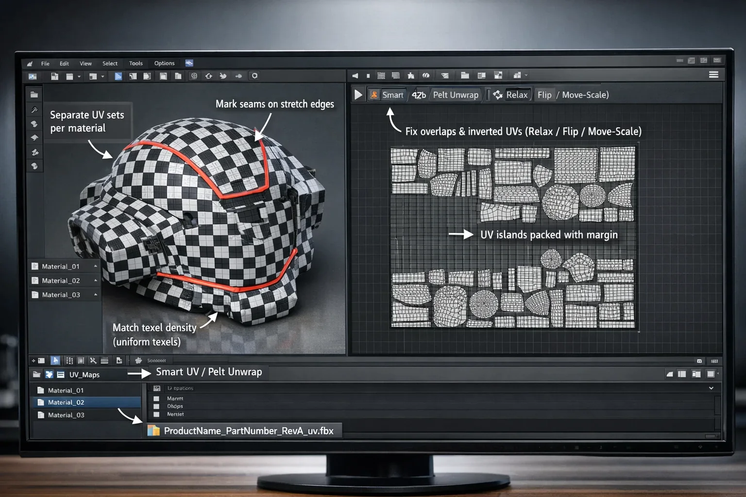
Choose an optimized mesh in your 3D program and change to UV Editing. UV unwrap manually to make a starting layout, using automatic UV unwrap, and then edit seams at the edges where the texture will be stretched. Apply the unwrapping tools such as Smart UV Project, Pelt Mapping, or UV Pack, so that the mesh is flattened effectively. UV islands Scale islands to keep the amount of texels per area constant throughout all the areas so that the textures are smooth and even when rendered. Split various materials or components into different UV sets in case it is needed to texturize many surfaces. Identify overlapping and inverted UVs and correct them with UV Relax, Flip, or Move/Scale. Copy the UV layouts as the editable files in a special folder named UV_Maps with the same file naming convention with a suffix of the file being the UV (eg, ProductName Part Number RevA uv.fbx). These steps will make the mesh ready to receive the texture mapping and the application of the PBR materials without distortion or marketing render mistakes.
Step 7: Material and Texture Creation
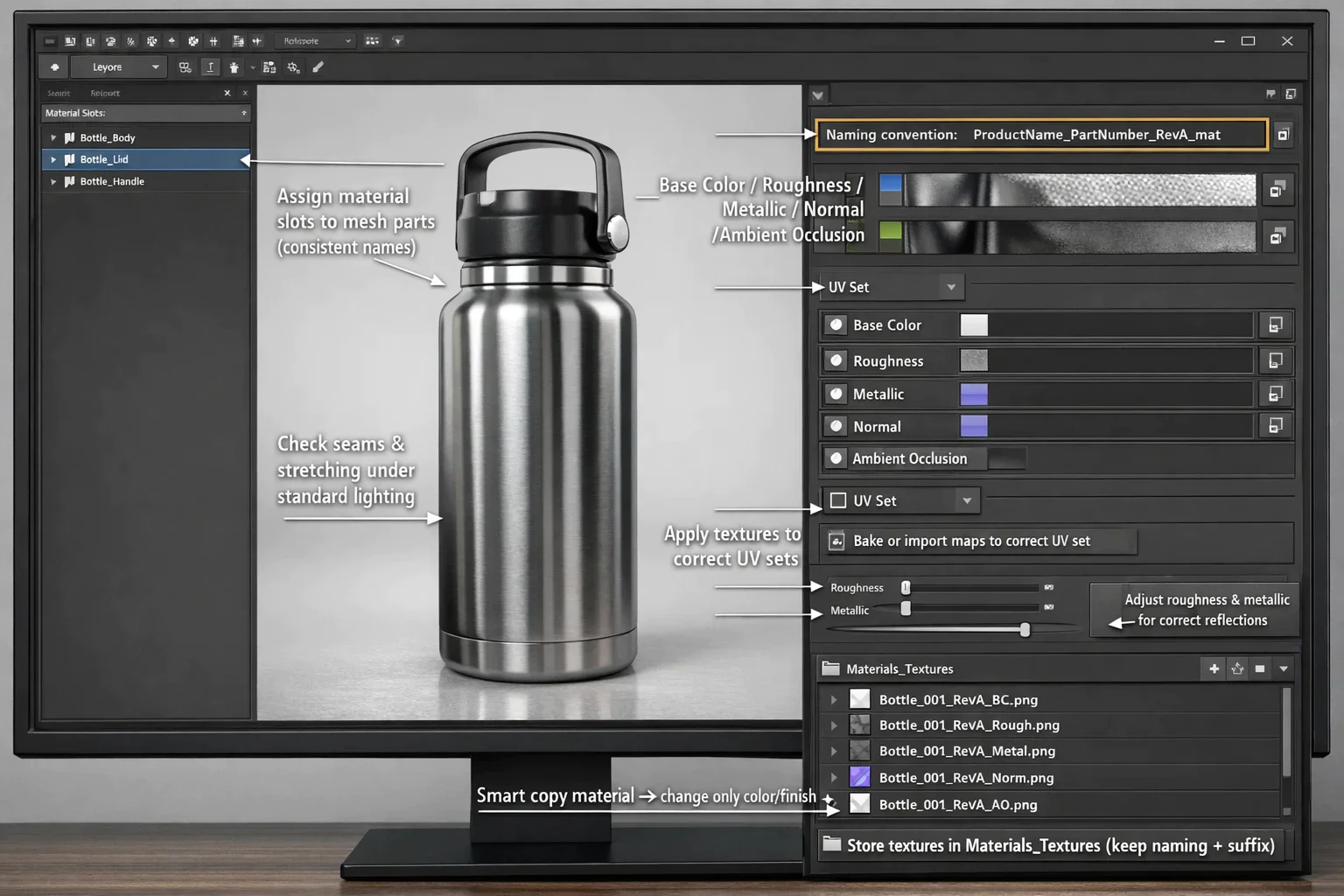
Open your optimized mesh with UV maps applied in your 3D production or texturing software (e.g., Substance Painter, Blender, 3ds Max). Assign each material slot to the corresponding mesh part using consistent naming conventions. Create PBR materials by defining Base Color, Roughness, Metallic, Normal, and Ambient Occlusion maps. Import or bake textures as needed, and apply them to the correct UV sets. Real-time adjustment of material parameters, proper reflections, roughness, and surface response, even under standard lighting. To create a number of variants, just smartcopy the material setup and change only the properties that need to be changed (e.g., a color or a finish). Store all material configurations and textures in a separate Materials_Textures folder, keeping the original file naming criteria but adding a suffix of sound material (e.g., ProductNamePartNumberRevAmat). Make sure that all the textures are showing up properly, either under preview or render, and that no seams or stretching are being experienced. Following these steps will result in your meshes being full of texture and prepared for marketing images, and will be consistent, realistic, and reusable across all platforms.
Step 8: Scale, Orientation, and Scene Setup
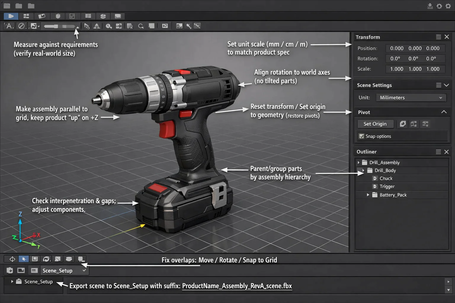
Open your textured mesh in the 3D production software and change to the Scene or Transform panel. Enhance each mesh or assembly and measure the unit scale to the product requirements (ex, millimeters, centimeters, or meters). Restore all pivot points by choosing the mesh and choosing Reset Transform or Set Origin to Geometry, which makes sure that the mesh is properly rotated and aligned in the scene. Make the mesh parallel to the axes of world coordinates with the product in the positive Z-axis (or whichever way suits your usual project positioning). Create group or parent meshes based on the assembly hierarchy in order to have the right relationships.
Look at the overlaps, interpenetration, or misaligned components and fix them with the help of Move, Rotate, or Snap to Grid tools. Copy the complete aligned and sized scene into a specific folder called Scene_Setup with a suffix of scene (i.e. ProductName_Assembly_RevA_scene.fbx). With the help of these steps, you will make sure that every marketing-ready 3D asset is properly scaled, oriented, and hierarchical so that it can be rendered, integrated into AR/VR and other pipelines to visualize the data.
Step 9: Export Marketing-Ready 3D Assets
Load your completed and aligned scene of full texture into the 3D production program, then choose the full assembly or each mesh separately. Go to File/Export, where one can select the target format to be used on marketing platforms, including FBX, OBJ, GLTF, or USD. Export environment:t Enabling textures on the images, preserving hierarchy, transforms, and unit scale. To create real-time applications, to create an LOD version, and to run the mesh in question and use the Decimate or Simplify Mesh tools, export the different LODs with an apparent suffix (i.e., _LOD0, _LOD1).
Put in a specific folder marked as Marketing_Assets all exported files with reasoning naming conventions (e.g. ProductName_PartNumber_RevA.fbx). Open one of the sample files in the target platform or the engine to make sure that the textures, materials, pivots, and hierarchy of textures are read correctly. Doing these, you end up with the fully optimized, ready-to-use 3D materials that retain the accurate design, are lightweight, and successfully cover the marketing campaigns, renders, web viewers, or in AR/VR settings.
Step 10: Final Output and Validation
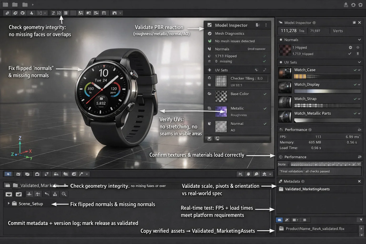
Load all marketing-ready 3D content in the target MA. Ensure all of the geometries in all models are integumentous with no missing face normals, flipped normals, or any overlaps between meshes. Check that there is correct display of textures and materials; correct PBR reactions, correct UV positions, and no stretching and seams. Make certain that scale, pivots, and orientation are in accordance with the real-world product specification and designed scene configuration. In the case of real-time apps, frame rate test performances and load times are required to meet what the platform requires. Commit any metadata or version control logs, and the last release turns out to be validated.
Copy one copy of all verified assets into the folder named Validated_Marketing Assets with the transparent naming convention (ex, ProductName_RevA validated.fbx). In doing so, you are checking that all of your 3D assets are correct, properly optimized, and that they are completely market campaignable, web visualization, AR/VR integration, or interactive product configurators.
Conclusion
Creating a cohesive CAD-through-marketing 3D pipeline is a key factor in combining engineering accuracy and artistic visualization work was built to work together harmoniously. A carefully developed workflow, choosing a master CAD source, optimizing and cleaning a model, UV wrapping, texturing, and end export allows the team to create a 3D asset that is lightweight, correct, and usable, forming an accurate model and reusable parts of the project.
The method minimizes mistakes, time loss, and ensures only one source of truth, hence, resulting in comprehensive and quality 3D content difficult to alter, irrespective of the render 3D, AR/VR, and marketing campaigns. Finally, a properly developed pipeline provides the cooperation between the engineers and marketers with a solution that is not just technically accurate but also appealing to the eyes.